Only one serving cell per UE
Same for UL and DL
»UE does not receive DL data or UL ACKs from multiple cells
UE cannot transmit to multiple cells with single Tx chain in asynchronous deployments
»Single carrier waveform in uplink
L2 handover
Network based
» UE assisted
UE based
»UE performs HO autonomously

menu_web

LTE E-UTRA Synchronized Random Access
The E-UTRA Random Access procedure is specified mainly in the MAC layer only!

LTE E-UTRA Random Access
•Random Access can be triggered by:
• PDCCH order (i.e., handover)
• UE MAC sublayer (i.e., initial access)
•Two types of Random Access:
• Synchronized:
– The PDCCH order or RRC optionally indicate a Random Access Preamble and PRACH resource
– When Random Access Preamble and PRACH resource are explicitly signaled, it is contention free
• Unsynchronized
– UE selects a Random Access Preamble and PRACH resource
Select one of the two groups of Random Access Preambles configured by RRC
Randomly select a Random Access Preamble within the selected group
Contention resolution is needed
E-UTRA Random Access
More information can be found in TS36.321 Section 5.1.
LTE E-UTRA UL Closed Loop Power Control
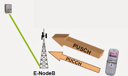
• UE transmits PUCCH or PUSCH.
• Serving E-NodeB monitors link quality and takes into account the overload indicators (over X2) from neighbor cells.
• Serving E-NodeB sends Transmit Power Control commands (TPC) as part of Downlink Control Information (DCI) on PDCCH.
• UE adjusts transmit power levels of PUCCH or PUSCH.
• Go back to 1.
Single Serving Cell No Soft Handover No Macro-diversity]

LTE E-UTRA UL Scheduled Operation (Link Adaptation)
• UE sends SR (Scheduling Request – part of Uplink Control Information), BSR (Buffer Status Report) and PHR (Power
Headroom Report) on PUCCH (or starts random access if no PUCCH is configured).
• Scheduler at E-NodeB dynamically allocates UL resources to UE:
– Grant is assigned to UE on PDCCH.
– Assigned resources (PRB and MCS) are communicated to the UE.
• UE sends user data on PUSCH.
• If E-Node B decodes the Uplink data successfully, it changes the New Data Indicator (NDI) on PDCCH, and/or
PUCCH Physical Uplink Control Channel sends ACK/NAKs on PHICH.
PDCCH Physical Downlink Control Channel
PUSCH Physical Uplink Shared Channel
PHICH Physical HARQ ACK/NAK Indicator Channel
LTE E-UTRA Uplink Operation Highlights
• Link Adaptation (CDS – Channel Dependent Scheduling)
– Adaptive transmission Bandwidth
– Adaptive Modulation and Channel Coding Rate (AMC)
– Meets QoS requirements
• UL Power Control
– Intra-cell power control: the power spectral density of the Uplink transmissions can be influenced by the eNB.
• UL Timing Control
– Objective is to compensate for propagation delay and thus time-align the transmissions from different UEs with the receiver window of the eNB.
– The timing advance is derived from the UL received timing and sent by the eNB to the UE. UE uses this information to advance/delay its timings of transmissions to the eNB.
• Random Access procedure
LTE PRACH
PRACH:
• The preamble format determines the length of the Cyclic Prefix and Sequence
• FDD has 4 preamble formats (for different cell sizes) and 16 RA slot configurations (for different bandwidth)
• The start of Random Access Preamble transmission assumes Timing Advance = 0 except for handover that UE can assume a time difference between current cell and target cell
• Each random access preamble occupies a bandwidth corresponding to 6 consecutive resource blocks
• The diagram considers RACH structure for FDD
LTE Sounding Reference Signals (SRS)
SRS shall be transmitted at the last symbol of the subframe.
PUSCH:
• The mapping to resource elements only considers those not used for transmission of reference signals.
PUCCH Format 1a and 1b (HARQ-ACK):
• One SC-FDMA symbol on PUCCH shall be punctured.
PUCCH Format 1 (SR) and 2, 2a, 2b (CQI):
• A UE shall not transmit SRS whenever SRS collide with PUCCH format 1 (SR), and 2, 2a and 2b (CQI).


LTE E-UTRA Uplink Reference Signals
•Two types of E-UTRA/LTE Uplink Reference
Signals:
• Demodulation reference signal
– Associated with transmission of PUSCH or PUCCH
– Purpose: Channel estimation for uplink coherent demodulation/detection of the uplink control and data channels
– Transmitted in time/frequency depending on the channel type (PUSCH/PUCCH), format, and cyclic prefix type
• Sounding reference signal
– Not associated with transmission of PUSCH or PUCCH
– Purpose: Uplink channel quality estimation feedback to the uplink scheduler (for Channel Dependent Scheduling) at the e-NodeB
– Transmitted in time/frequency depending on the SRS bandwidth and the SRS bandwidth configuration (some rules apply if overlap with PUSCH and PUCCH)
Notes
•The same set of base sequences is used to generate demodulation and sounding reference signals
•The base sequences and the reference signals are derived from Zadoff-Chu sequences
•Cyclic shifts can be applied to a base sequence to obtain multiple reference signal sequences

LTE Uplink Channelization Hierarchy

LTE E-UTRA UL Waveform: SC-FDM
• OFDM based UL transmission would lead to higher Peak-to- Average Power Ratio (PAPR) than the SC-FDM (TR25.814 Section 9.2.1.4).
• Single Carrier Waveform (SC-FDM or DFT-spread OFDM)
– Requires Data and control channels to be multiplexed prior to the DFT operation at the transmitter
• “Price” of maintaining Single Carrier Waveform
– 32 channel combinations == Multiplexing “rules”
» Data, ACK, CQI, SRS, SR
» No channel can be transmitted independently of the other
• Data and UL Demodulation Pilots (Reference Signals) are TDM
In OFDM each sub-carrier carries information from a specific modulation symbol and given the nature of this OFDM signal the PAPR due to the simultaneous transmission of multiple carriers can be significant.
In SC-FDM each sub-carrier carries information from all transmitted modulation symbols since the latter are spread by the DFT operation and then mapped to each sub-carrier. This single carrier transmission achieved by an IDFT operation followed by an FFT operation results in a lower PAPR. Careful multiplexing of data and control information is required for SC-FDM transmission.
LTE E-UTRA UL Channels and Signals
Signals
• Demodulation Reference Signal (DM-RS)
• Sounding Reference Signal (SRS) Control
• ACK, CQI, Rank Indicator (RI), Precoding support (PMI)
• Scheduling Request (SR)
• Single “control” channel
- Physical Uplink Control Channel (PUCCH) Data
• Unicast data and data + control
• Single “data” channel
- Physical Uplink Shared Channel (PUSCH) Random access
• Preamble sequences in Physical Random Access Channel (PRACH)
LTE ACK/NACK for PDSCH Transmissions
The UE shall, upon detection of a PDSCH transmission in subframe n-4 intended for the UE and for which an ACK/NACK shall be provided, transmit the ACK/NACK response in subframe n.
CQI/PMI/RI and ACK/NACKs multiplexing on PUCCH is possible:
• Format 2:
– CQI/PMI/RI not multiplexed with ACK/NAK
• Format 2a/2b
– CQI/PMI/RI multiplexed with ACK/NAK (normal CP)
• Format 2:
– CQI/PMI or RI multiplexed with ACK/NAK (extended CP)
ACK/NACK for PDSCH Transmissions
The UE shall, upon detection of a PDSCH transmission in subframe n-4
intended for the UE and for which an ACK/NACK shall be provided,
transmit the ACK/NACK response in subframe n.
ACK/NACKs alone can be delivered PUCCH format 1a and 1b
LTE E-UTRA DL Scheduling Principles
Dynamic Scheduling: E-UTRAN dynamically allocates resources (PRBs and MCS) to UEs at each TTI via the C-RNTI on PDCCH(s)
• UE monitors the PDCCH(s) in order to find possible allocation when its downlink reception is enabled (activity governed by DRX when configured) Semi-persistent Scheduling: Initially PDCCH indicates if the DL grant can be implicitly reused in the following TTIs according to the periodicity defined by RRC
• RRC defines the periodicity of the semi-persistent DL grant
– Characterized by a start frame number, periodicity and packet format (one or more may be defined)
• Retransmissions are explicitly signalled via the PDCCH(s).
For persistent assignments
In the sub-frames where the UE has semi-persistent downlink resource, if the UE cannot find
its C-RNTI on the PDCCH(s), a downlink transmission according to the semi-persistent
allocation that the UE has been assigned in the TTI is assumed.
in the sub-frames where the UE has semi-persistent downlink resource, if the UE finds its CRNTI
on the PDCCH(s), the PDCCH allocation overrides the semi-persistent allocation for
that TTI and the UE does not decode the semi-persistent resources.
LTE CQI/PMI/RI Reporting Overview
Reporting on PUSCH
- Aperiodic Reports
-Wideband CQI (multiple-PMI per subband)
-UE Selected Subband CQI (No-PMI, Multiple-PMI)
-Higher Layer Configured Subband CQI (No-PMI, Single-PMI)
-Frequency selective/non-selective scheduling
Reporting on PUCCH
-Periodic Reports
-Wideband CQI (No-PMI, Single-PMI)
-UE Selected Subband CQI (No-PMI, Single-PMI)
-Frequency selective/non-selective scheduling
LTE DL Scheduled Operation Overview
1. UE reports CQI (Channel Quality Indicator), PMI (Pre-coding Matrix Index) and RI (Rank Indicator) in
PUCCH (or PUSCH if there is UL traffic)
2. Scheduler at E-NodeB dynamically allocates resources to UE:
- UE reads PCFICH every subframe and finds out the number of OFDM symbols occupied by PDCCH
- UE finds about TX Mode and assigned resources (PRB and MCS) reading PDCCH
3. E-NodeB sends user data in PDSCH
4. UE attempts to decode the received packet and sends ACK/NACK using PUCCH (or PUSCH if there is UL traffic)

LTE DL Operation Highlights: Similarities to HSPA
• Shared Channel Operation
• CDS (Channel Dependent Scheduling)
–Requires Channel Quality Information (CQI) sent on the UL
–Requires Pre-coding and Rank information sent on the UL for MIMO
• AMC (Adaptive Modulation and Coding)
–Requires informing the UE about allocated Resources
–Requires informing the UE about Modulation and Coding Schemes (MCS)
• HARQ (Hybrid ARQ)
–Uses Asynchronous adaptive retransmissions
–Uses Synchronous ACK/NAKs
–Requires ACK/NAK sent on the UL
• DL Modulation: QPSK, 16-QAM, 64-QAM
- Availability and Error Performance Objective
I- Hypothetical Reference Path/Connection
នៅក្នុង
27500km នៃ hypothetical reference path (ITU
G.282), គេចែក reference length 2500km សំរាប់
radio។ ក្នុងនោះ National portion (ITU-R) ចែកជា short
haul, medium haul និង long haul។

- LTE DL Reference Signals: TX Antenna
DL Reference Signals: 1 TX Antenna
 DL RS transmitted on 2 OFDM symbols every slot
• 6 subcarrier spacing
Cell-specific DL Reference Signal (Common Pilots, FS1 and FS2)
Time and Frequency resource allocations:
– Allocated on a per Antenna port basis: {0, 1, 2, 3, 4} physical antenna ports
– Antenna 0 and 1 transmitted on 2 OFDM symbols every slot
6 subcarrier spacing and 2x staggering (45 kHz freq sampling)
– Antenna 2 and 3 transmitted on 1 OFDM symbol in every slot
6 subcarrier spacing with 2x staggering across slots
– Same frequency spacing for normal and extended CP numerologies
DL Reference Signals: 2 TX Antenna

DL Reference Signals: 4 TX Antenna

Downlink Transmission – An Example
Example of Frame Structure Type 1 (extended CP) transmission

Downlink Transmission – An Example
The slide shows how a subframe FS1 (extended CP) ends up being transmitted. Observe the first
OFDM symbol cell-specific reference signal, PCFICH, informing the assigned UEs of the
corresponding PDCCH format. Also PDCCH is transmitted in the first 1-3 OFDM symbols
carrying resource allocation and MCS to the corresponding allocated UEs.
• 6 subcarrier spacing
Cell-specific DL Reference Signal (Common Pilots, FS1 and FS2)
Time and Frequency resource allocations:
– Allocated on a per Antenna port basis: {0, 1, 2, 3, 4} physical antenna ports
– Antenna 0 and 1 transmitted on 2 OFDM symbols every slot
6 subcarrier spacing and 2x staggering (45 kHz freq sampling)
– Antenna 2 and 3 transmitted on 1 OFDM symbol in every slot
6 subcarrier spacing with 2x staggering across slots
– Same frequency spacing for normal and extended CP numerologies
DL Reference Signals: 2 TX Antenna
DL Reference Signals: 4 TX Antenna
Downlink Transmission – An Example
Example of Frame Structure Type 1 (extended CP) transmission
Downlink Transmission – An Example
The slide shows how a subframe FS1 (extended CP) ends up being transmitted. Observe the first
OFDM symbol cell-specific reference signal, PCFICH, informing the assigned UEs of the
corresponding PDCCH format. Also PDCCH is transmitted in the first 1-3 OFDM symbols
carrying resource allocation and MCS to the corresponding allocated UEs.
- LTE Physical HARQ Indicator PHICH
Used for ACK/NAK of UL-SCH transmissions
Transmitted in
• Time
– Normal duration: 1st OFDM symbol
– Extended duration: Over 2 or 3 OFDM symbols
• Frequency
– Spanning all system bandwidth
– Mapping depending on Cell ID
FDM multiplexed with other DL control channels
Support of CDM multiplexing of multiple PHICHs
• PHICHs mapped to same resources constitute a PHICH group.
• Coding: ACK bit repeated 3 times before “spreading”
• Spreading of coded bits using Hadamard codes
– SF = 4 for normal CP (results in 12 RE)
– SF = 2 for extended CP (results in 6 RE)

- LTE Physical Downlink Shared Channel (PDSCH)
Used to transmit DL packet data
• One Transport Block transmission per UE’s code word per subframe
• A common MCS per code word per UE across all allocated RBs
– Independent MCS for two code words per UE
• 7 PDSCH TX modes
Mapping to Resource Blocks (RBs)
• Mapping for a particular transmit antenna port shall be in increasing order of:
– First the frequency index and then the time index, starting with the first slot in a subframe.
- LTE Physical Downlink Control Channel (PDCCH)
Used for:
• DL/UL Resource Assignments
• Multi-user Transmit Power Control (TPC) commands
• Paging indicators
Different PDCCH formats are defined:
• 1-3 OFDM symbols in a sub-frame
• PCFICH using the first OFDM symbol of each subframe informs PDCCH specific format
PDCCHs are constructed as follows
• CCE is defined as a unit of 36 REs
• A PDCCH instance is constructed as 1, 2, 4 or 8 CCEs

PDCCH Carries DCI – Downlink Control Information
Uplink assignments:
– RB assignment, transport block size, retransmission sequence number, power control command, cyclic shift
of DM RS for SDMA, etc.
Downlink assignments:
– RB assignment, transport block size, HARQ process number, Redundancy Version index, Uplink power
control command
Uplink Power Control Commands
Paging Indicator
L1/L2 control channel for:
DL scheduling, including:
– Regular unicast data
– Scheduling of Paging messages
Acting as a “paging indicator”
– Scheduling of SIBs
– Scheduling of random access responses
UL grants, including:
– Regular unicast data
– Requests for aperiodic CQI reports
Multi-user TPC commands:
– TPC commands for PUCCH or PUSCH for multiple UEs
- LTE Physical Control Format Indicator (PCFICH)
Used for Signaling the PDCCH control
region:
• 1, 2 or 3 OFDM symbols for overall TX BW > 10 RBs
• Control region quantized to full OFDM symbols
– Control and data do not occur in same OFDM symbol
Transmitted in:
• Time: 1st OFDM symbol of all subframes
• Frequency: spanning the entire system band
– 4 REGs 16 REs
– Mapping depending on Cell ID

- LTE Physical Broadcast Channel (PBCH)
Carries the Broadcast Transport Channel
• Overall DL transmission bandwidth
• Number of transmit antennas
• DL-RS Transmit Power
• System Frame Number, etc Transmitted in
• Time: subframe 0 in every radio-frame
– 4 OFDM symbols in the subframe
• Frequency: middle 1.08MHz (6 RBs)
TTI = 40 ms
• Transmitted in 4 bursts at a very low data rate Transmission such that
• Every burst is self-decodable
• CRC check uniquely determines the 40ms PBCH TTI boundary

- LTE Synchronization Signals (SCH)
Used for Initial System Acquisition
• Time/frequency synchronization
– Carrier frequency determination
– OFDM symbol/subframe/frame timing
• Cell ID determination (504 Possible cell IDs)
– Cell-IDs are grouped into 168 unique physical layer cell-identity groups, each group
contains 3 unique IDs (168*3 = 504) Transmitted in
• Time: subframe 0 and 5 in every radio-frame
• Frequency: middle 1.08MHz (6 RBs)
Primary synchronization signal (TX on P-SCH)
• Provides the cell ID within the cell ID group (1 of 3)
• Transmitted in last OFDM symbol of subframes 0 and 5 (provides sub-frame timing)
Secondary synchronization signal (TX on S-SCH)
• Provides the 168 cell ID group information
• M-sequences with scrambling (different “generation” method for SF0 and SF5, provides frame timing)
Cell ID Determination using P-SCH and S-SCH Signals
There are 504 unique physical-layer cell identities. The physical-layer cell identities are grouped into 168 unique physical-layer cellidentity
groups, each group containing 3 unique identities (168*3 = 504) . The grouping is such that each physical-layer cell identity is part
of one and only one physical-layer cell-identity group. A physical-layer cell identity is thus uniquely defined by a number in the range of 0
to 167, representing the physical-layer cell-identity group, and a number in the range of 0 to 2, representing the physical-layer identity
within the physical-layer cell-identity group.
Acquisition Procedure
The initial cell search begins after the UE is switched on. At this time the UE does not know anything about the
cells around it and it begins to look for strong cells in the DL band.
Once the UE has found a good candidate with strong 72 subcarriers (6x12) that might carry the synchronization
sequences and the BCH, the UE performs a rough frequency synchronization.
The UE looks for the Primary Synchronization Channel (P-SCH). Once it has found it, it knows the exact carrier
frequency and the timing of the slot 0 or 10. By trial and error, the UE also knows the CP configuration.
During the previous process, the UE also performed the first step to find the Physical Layer cell ID. Each of the 3
P-SCH sequences is linked to one group member of the 168 different cell ID groups.
The next step is to detect the S-SCH. The SCH is transmitted 1 OFDM symbol before the
P-SCH. Once S-SCH is detected, the radio frame and the Physical Layer cell ID are perfectly known.
The UE is ready to read BCH at this time and can also read the PLMN ID from the system information on the
BCCH.
UE registers in the cell.
Additional information about Synchronization Sequences
Primary Synchronization Signal uses:
- Frequency domain Zadoff-Chu sequence of length 62
Secondary Synchronization Signal uses:
- Interleaved concatenation of two length-31 binary sequences. The concatenated sequence is scrambled with a scrambling sequence given by the primary synchronization signal.
- The combination of the two length-31 sequences defining the secondary synchronization signal differs between subframe 0 and
subframe 5. according tothe method of interleaving (This difference helps the UE to identify the start of a new frame)
- LTE Downlink Physical Channels LTE vs. HSPA

Downlink Control Channels Operation Support
Support for DL Operation
PDCCH transmits information about Resource allocation, HARQ info, Transport format, and implicitly the RNTI for the DL
transmission. Similar to HS-SSCH functionalities in HSDPA.
In support of MIMO, there is also some additional information transmitted: 1) The codebook entry, and 2) The transmission
rank of the following DL packet.
Support for UL Operation
PDCCH can also transmit scheduling grants to the UE. In LTE there is a need to explicitly signal the UL granted resources
differently than HSPA (CDMA-based) where only Allowed Power levels are granted. Multiple UEs cannot simultaneously
access same subcarriers in an uncontrolled manner. The scheduling grants in HSUPA are managed through E-AGCH and the
E-RGCH.
PDCCH has many functionalities and not all of them are used at the same time. Hence, PDCCH requires flexibility with
regard to possible configurations. This results in a variable size of the PDCCH and requires an additional channel to inform
the UE of a specific configuration. The PCFICH signals how many OFDM symbols (0-3) are occupied by the PDCCH.
Support for UL HARQ
PHICH sends acknowledgments on DL for UL UE transmitted data. Similar functionality as E-HICH in HSPA.
Additional Physical Channels
- Physical Broadcast Channel (PBCH)
– Carrying part of BCH
- Physical Multicast Channel (PMCH)
– Carrying MCH (MBSFN multicast)
Signals
- Reference Signal (RS) (a.k.a Pilots)
- Synchronization signals
– Primary Synchronization Signal (PSC)
– Secondary Synchronization Signal (SSC)
- LTE Downlink Channelization Hierarchy
Most DL data traffic is carried on the Down Link Shared Channel (DL-SCH) transport channel and
its corresponding Physical Downlink Shared Channel or PDSCH

are offered by the MAC layer)
Different kinds of data transfer services as offered by MAC. Each logical
channel type is defined by what type of information is transferred
Control Channels (for the transfer of control plane information)
Traffic Channels (for the transfer of user plane information)
CONTROL LOGICAL CHANNELS (C-Plane information)
– Broadcast Control Channel (BCCH)
- System information
– Paging Control Channel (PCCH)
- Paging information
– Multicast Control Channel (MCCH)
- Point-to-multipoint channel for MBMS control
information
– Dedicated Control Channel (DCCH)
- Unicast control channel
– Common Control Channel (CCCH)
- Point-to-multipoint channel used before RRC
connection established
TRAFFIC LOGICAL CHANNELS (U-Plane information)
– Dedicated Traffic Channel (DTCH)
- Unicast traffic channel
– Multicast Traffic Channel (MTCH)
- Point-to-multipoint channel for MBMS traffic
TRASPORT CHANNELS (How different type of information is going to transferred over the Air Interface) The physical layer offers information transfer services to MAC and higher layers. The physical layer
transport services are described by how and with what characteristics data are transferred over the radio interface:
Broadcast Channel (BCH) characterized by:
- fixed, pre-defined transport format; requirement to be broadcast in the entire coverage area of the cell.
Downlink Shared Channel (DL-SCH) characterised by:
- support for HARQ;
- support for dynamic link adaptation
- possibility to use beamforming;
- support for both dynamic and semi-static resource allocation;
- support for UE discontinuous reception (DRX) to enable UE power saving;
- Support for MBMS transmission.
NOTE: The possibility to use slow power control depends on the physical layer.
Paging Channel (PCH) characterised by:
- support for UE discontinuous reception (DRX) to enable UE
power saving (DRX cycle is indicated by the network to the
UE);
- Requirement to be broadcast in the entire coverage area of
the cell;
- mapped to physical resources which can be used
dynamically also for traffic/other control channels.
Multicast Channel (MCH) characterised by:
- requirement to be broadcast in the entire coverage area of the cell;
- support for MBSFN combining of MBMS transmission on multiple cells;
- support for semi-static resource allocation e.g. with a time frame of a long cyclic prefix.
Physical Channels Control Related Information: CFI – Control Format Indicator is transmitted in PCFICH
HI - HARQ Indicator is transmitted in PHICH
DCI – Down Link Control Indicator is transmitted in PDCCH
UCI – Uplink Control Information sent on PUCCH/PUSCH
- LTE (E-UTRA) Essentials
LTE (E-UTRA) Air Interface Capabilities
Bandwidth support
• Flexible from 1.4 MHz to 20 MHz
Waveform
• OFDM in Downlink / SC-FDM in Uplink
Duplexing mode
• FDD: full-duplex (FD) and half-duplex (HD)
• TDD
Modulation orders for data channels
• Downlink: QPSK, 16QAM, 64QAM
• Uplink: QPSK, 16QAM, 64QAM
MIMO support
• Downlink: SU-MIMO and MU-MIMO (SDMA)
• Uplink: SDMA
UE eNodeB Communication Link
Single (and same) link of communication for DL & UL
Effectively:
• DL serving cell = UL serving cell
• No UL or DL macro-diversity
– UL softer HO reception is an implementation choice
– UE’s “Active Set” size = 1
• Hard-HO-based mobility
– RACH-based mobility procedure to target cell
– Network controlled by default
– UE initiated under RL failure condition
• Load indicator for inter-cell load control
– Transmitted over X2 interface
E-UTRA Air Interface Peak Data Rates
Downlink
• ~300 Mbps in 20 MHz
• Assumptions:
– 4 stream MIMO
– 14.29% Pilot overhead
(4 TX antennas)
– 10% common channel
overhead
Note that this overhead
level is adequate to serve
1 UE/subframe.
– 6.66% waveform overhead
(CP + window)
– 10% guard band
– 64QAM code rate ~1
Uplink
• ~75 Mbps in 20 MHz
• Assumptions:
– 1 TX antenna
– 14.3% Pilot overhead
– 0.625% random access
overhead
– 6.66% waveform overhead
(CP + window)
– 10% guard band
– 64QAM code rate ~1
Time Domain Organization
Radio Frame has two Structures:
• Type 1 (FS1) for FDD DL/UL
• Type 2 (FS2) for TDD
This presentation deals only with FS1

Time Domain Organization
Basic unit of time Ts, defined with relation to 20 MHz, 15 KHz inter-subcarrier separation and
2048 FFT size (36.211)
Ts = 1/(15e3*2048) = 32.55 ns Number of samples in 10 ms is 10 ms/32.55 ns=307200
Tf = 307200Ts = 10 ms
Tslot = (307200/20)Ts = 15360Ts
Half radio frame = 5 ms
– Contains one sync channel instance
– Tailoring efficient HO from GSM
Radio frame = 10 ms
– Periodicity of sync channel
PBCH TTI = 40 ms
– Periodicity of primary broadcast channel
Frequency Domain Organization
LTE DL/UL air interface waveforms use a number of orthogonal subcarriers to
send user traffic data, Reference Signals (Pilots), and Control Information.

Channel Bandwidth and Transmission Bandwidth
More information can be found in TS36.101.
OFDM uses all the sub carriers for a single user, whereas OFDMA uses different sub carriers
for different users.
There are different types of sub carriers: Data, Pilot, Control, Null, etc.
There are two guard bands at the edges of the OFDM/OFDMA-signal (no RF transmission in
these sub carriers). Each guard band exists to avoid interference with adjacent bands.
Taking into account the guard band sub carriers and the DC sub carrier, the number of
available sub carriers is as shown in the table.
UL/DL Resource Grid Definitions

Resource Element (RE)
• One element in the time/frequency
resource grid
– One subcarrier in one OFDM/LFDM
symbol for DL/UL
Resource Block (RB)
• Minimum scheduling size for
DL/UL data channels
• Physical Resource Block (PRB)
– 180 kHz x 0.5 ms
12 subcarriers x 1 slot for
15 kHz subcarrier spacing
24 subcarriers x 1 slot for
7.5 kHz subcarrier spacing
Bandwidth support
• Flexible from 1.4 MHz to 20 MHz
Waveform
• OFDM in Downlink / SC-FDM in Uplink
Duplexing mode
• FDD: full-duplex (FD) and half-duplex (HD)
• TDD
Modulation orders for data channels
• Downlink: QPSK, 16QAM, 64QAM
• Uplink: QPSK, 16QAM, 64QAM
MIMO support
• Downlink: SU-MIMO and MU-MIMO (SDMA)
• Uplink: SDMA
UE eNodeB Communication Link
Single (and same) link of communication for DL & UL
Effectively:
• DL serving cell = UL serving cell
• No UL or DL macro-diversity
– UL softer HO reception is an implementation choice
– UE’s “Active Set” size = 1
• Hard-HO-based mobility
– RACH-based mobility procedure to target cell
– Network controlled by default
– UE initiated under RL failure condition
• Load indicator for inter-cell load control
– Transmitted over X2 interface
E-UTRA Air Interface Peak Data Rates
Downlink
• ~300 Mbps in 20 MHz
• Assumptions:
– 4 stream MIMO
– 14.29% Pilot overhead
(4 TX antennas)
– 10% common channel
overhead
Note that this overhead
level is adequate to serve
1 UE/subframe.
– 6.66% waveform overhead
(CP + window)
– 10% guard band
– 64QAM code rate ~1
Uplink
• ~75 Mbps in 20 MHz
• Assumptions:
– 1 TX antenna
– 14.3% Pilot overhead
– 0.625% random access
overhead
– 6.66% waveform overhead
(CP + window)
– 10% guard band
– 64QAM code rate ~1
Time Domain Organization
Radio Frame has two Structures:
• Type 1 (FS1) for FDD DL/UL
• Type 2 (FS2) for TDD
This presentation deals only with FS1
Time Domain Organization
Basic unit of time Ts, defined with relation to 20 MHz, 15 KHz inter-subcarrier separation and
2048 FFT size (36.211)
Ts = 1/(15e3*2048) = 32.55 ns Number of samples in 10 ms is 10 ms/32.55 ns=307200
Tf = 307200Ts = 10 ms
Tslot = (307200/20)Ts = 15360Ts
Half radio frame = 5 ms
– Contains one sync channel instance
– Tailoring efficient HO from GSM
Radio frame = 10 ms
– Periodicity of sync channel
PBCH TTI = 40 ms
– Periodicity of primary broadcast channel
Frequency Domain Organization
LTE DL/UL air interface waveforms use a number of orthogonal subcarriers to
send user traffic data, Reference Signals (Pilots), and Control Information.
Channel Bandwidth and Transmission Bandwidth
More information can be found in TS36.101.
OFDM uses all the sub carriers for a single user, whereas OFDMA uses different sub carriers
for different users.
There are different types of sub carriers: Data, Pilot, Control, Null, etc.
There are two guard bands at the edges of the OFDM/OFDMA-signal (no RF transmission in
these sub carriers). Each guard band exists to avoid interference with adjacent bands.
Taking into account the guard band sub carriers and the DC sub carrier, the number of
available sub carriers is as shown in the table.
UL/DL Resource Grid Definitions
Resource Element (RE)
• One element in the time/frequency
resource grid
– One subcarrier in one OFDM/LFDM
symbol for DL/UL
Resource Block (RB)
• Minimum scheduling size for
DL/UL data channels
• Physical Resource Block (PRB)
– 180 kHz x 0.5 ms
12 subcarriers x 1 slot for
15 kHz subcarrier spacing
24 subcarriers x 1 slot for
7.5 kHz subcarrier spacing
- LTE Network Architecture: Evolution & Protocols
3GPP UMTS and WCDMA Releases & Features

Release 99 – Specified the first UMTS 3G networks, incorporating a CDMA air interface.
Release 4 – Introduced mainly the CS Core Network split feature plus other minor enhancements.
Release 5 – Introduced mainly IMS, HSDPA (allowing broadband services on the Downlink), and other
minor enhancements.
Release 6 – Integrated operation with Wireless LAN networks and added HSUPA (enables broadband
uploads and services), MBMS, and enhancements to IMS such as Push-to-Talk over Cellular (PoC), video
conferencing, messaging, etc.
Release 7 – Significant progress made in 2006 and 2007 toward completion of this release. Most documents
are under revision control. Introduced, among other features, enhancements to High-Speed Packet Access
(HSPA+), QoS, and improvements to real-time applications like VoIP.
Release 8 – In progress (expected 2009). Introducing, among others, E-UTRA (also called LTE, based on
OFDMA), All-IP Network (also called SAE), and Femto cells operation. Release 8 constitutes a re-factoring
of UMTS as an entirely IP based fourth-generation network. 3GPP RAN approved the LTE Physical Layer
specifications in September 2007. The specifications are 36.201–36.214 and are on the 3GPP site at
http://www.3gpp.org/ftp/Specs/html-info/36-series.htm.
Each release incorporates hundreds of individual standards documents, each of which may have gone
through many revisions. Current 3GPP standards incorporate the latest revision of the GSM standards.
Standards documents are available for free on the 3GPP Web site. These standards cover the radio
component (Air Interface) and the Core Network, as well as billing information and speech coding down to
source code level. Cryptographic aspects (authentication, confidentiality) are also specified in detail. More
details about the 3GPP releases content can be found at http://www.3gpp.org/specs/releases-contents.htm
and http://www.3gpp.org/Management/WorkPlan.htm.
LTE and EPS Terminology
• Long Term Evolution (LTE): Evolution of 3GPP UMTS
Terrestrial Radio Access (E-UTRA) technology
• Evolved Packet System (EPS): Evolution of the
complete 3GPP UMTS Radio Access, Packet Core and
its integration into legacy 3GPP/non-3GPP networks.
It includes:
– Radio Access Network – Evolved UTRA Network (E-UTRAN)
– System architecture – Evolved Packet Core (EPC)
• This course uses the terms LTE and E-UTRA
interchangeably.
E-UTRA Design Performance Targets
• Scalable transmission bandwidth (up to 20 MHz)
• Improved Spectrum Efficiency
– Downlink (DL) spectrum efficiency should be 2-4 times Release 6 HSDPA.
Downlink target assumes 2x2 MIMO for E-UTRA and single TX antenna with Type 1
receiver HSDPA.
– Uplink (UL) spectrum efficiency should be 2-3 times Release 6 HSUPA.
Uplink target assumes 1 TX antenna and 2 RX antennas for both E-UTRA and
Release 6 HSUPA.
• Coverage
– Good performance up to 5 km
– Slight degradation from 5 km to 30 km (up to 100 km not precluded)
• Mobility
– Optimized for low mobile speed (< 15 kph)
– Maintained mobility support up—to 350 kph (or even up to 500 km/h)
• Advanced TX schemes and multiple-antenna technologies
• Inter-working with existing 3G and non-3GPP systems
– Interruption time of real-time or non-real-time service handover between
E-UTRAN and UTRAN/GERAN shall be less than 300 or 500 ms.
User Throughput and Spectrum Efficiency Requirements
Detailed throughput requirements:
Downlink:
– 5%-tile Downlink user throughput per MHz 2-3 times Release 6 HSDPA
– Average Downlink user throughput per MHz 3-4 times Release 6 HSDPA
– Downlink spectrum efficiency should be 3-4 times Release 6 HSDPA
– Downlink performance targets assume 2 transmit and 2 receive antennas for E-UTRA, and 1 transmit and
enhanced Type 1 receiver for Release 6 HSDPA
– Downlink user throughput should scale with spectrum allocation
Uplink:
– 5%-tile Uplink user throughput per MHz 2-3 times Release 6 HSUPA
– Average Uplink user throughput per MHz 2-3 times Release 6 HSUPA
– Uplink spectrum efficiency should be 2-3 times Release 6 HSDPA
– Uplink performance targets assume 1 transmit and 2 receive antennas for both E-UTRA and Release 6
HSDPA
– Uplink user throughput should scale with spectrum allocation and mobile maximum transmit power
E-UTRA is expected to outperform Release 6 HSPA by a factor of 2-4 in user throughput and spectrum efficiency.
This assumes a maximum cell range up to 5 km. For cell ranges up to 30 km, slight degradations are expected for the
achieved performance for the user throughput targets and more significant degradation for the spectrum efficiency
targets. However, cell ranges up to 100 km should not be precluded by the specifications.
3GPP Network Architecture Evolution

Faster RRM response for CDS
Reduced packet latencies
Network Architecture Evolution (decentralization process)
From a centric RNC-Based RRM (stupid Base Stations and smarter RNCs)
To a decentralized Base Station-based RRM (smarter Base Stations, less smart RNCs)
From user packet data forwarding to GGSN through RNC (intermediary RNCs)
To direct user packet data forwarding to GGSN (Direct Tunneling)
Enhanced Node B (eNB) Functions
 • Radio Resource Management:
 – Radio Bearer Control
– Admission/congestion control
– Connection and mobility control
– UL/DL dynamic scheduling
• IP header compression and
encryption of user data
• Selection of an MME at UE
attachment (if necessary)
• Routing of User Plane data towards
S-GW
• Routing of paging messages from
MME towards UE
• Measurement and reporting
configuration
Reference 23.401
eNB (Evolved Node B) provides the E-UTRA User Plane (PDCP/RLC/MAC/PHY) and
Control Plane (RRC) protocol terminations towards the UE.
The eNBs are logically interconnected with each other by means of the X2 interface.
The eNBs are also connected by means of the S1 interface to the EPC (Evolved Packet Core), more specifically to the MME (Mobility Management Entity) by means of the S1-MME and to the Serving Gateway (S-GW) by means of the S1-U.
The S1 interface supports a many-to-many relation between MMEs / Serving Gateways and eNBs.
Serving Gateway (S-GW) & P-GW Functions
S-GW
handover
• Mobility anchoring for inter-3GPP mobility
• E-UTRAN Idle Mode Downlink packet buffering and
initiation of network triggered service requests
• Lawful interception
• Packet routing and forwarding
• Transport level packet marking in the UL and DL
• UL and DL charging per UE, PDN, and QCI
• Termination of U-plane packets
• Switching of U-plane for support of UE
mobility
P-GW
• Per-user based packet filtering
• Lawful interception
• UE IP address allocation
• DL rate enforcement based on AMBR
For more details, see
3GPP TS 23.401
MME Functions
• NAS signaling and its security
• AS Security Control
• Inter CN node signaling for mobility
between 3GPP access networks
• Idle mode UE Reachability (including
control and execution of paging
retransmission)
• Tracking Area List Management (idle and
active)
• PDN GW and Serving GW selection
• MME selection for handovers with MME
change
• Idle state mobility control
• SGSN selection for 3GPP handovers
• Roaming and Authentication
• EPS bearer management
For more details, see
3GPP TS 23.401
E-UTRAN Protocol Stack: User Plane

References:
• LTE-Uu: 36.201 (Physical Layer), 36.321 (MAC), 36.322 (RLC), 36.323 (PDCP)
• S1: 36.411 (Physical Layer), 36.414 (S1- Data Transport)
• X2: 36.421 (Physical Layer); 36.424 (X2 – Data Transport)
Transport Layer reference for the S1 and X2 Interfaces:
IP in E-UTRAN
- Used in user and control planes
- IP in E-UTRAN shall also support:
1. NDS/IP (Network Domain Security for IP): Sets up Confidentiality and Integrity for data exchange
between network entities
2. Diffserv (Differentiated Services): Enhancements of the IP protocol for QoS
References:
RFC2475, An Architecture for Differentiated Services
GTP (GPRS Tunneling Protocol) in E-UTRAN
- GTP goes over UDP/IP transport protocol stack
- No flow or error control or any mechanism to guarantee the data delivery of S1-U interface
- As a reminder in 3G, GTP is used over the Iu-PS interface (connection between RNC and SGSN)
E-UTRAN Protocol Stack: Control Plane

 References:
• LTE-Uu: 36.331 (RRC)
• S1: 36.412 (Signaling Transport),
36.413 (Application Protocol)
• X2: 36.422 (Signaling Transport),
36.423 (Application Protocol)
• IETF RFC 2960 (Stream Control
Transmission Protocol)
About the SCTP (Stream Control Transmission Protocol):
- It is a reliable connection-oriented transport protocol similar to TCP
- As TCP, SCTP implements Congestion and flow control, detection of data corruption and loss/duplication of packets
- SCTP connection needs to be set up connection between peers before actual data transmission (as TCP)
- From functional perspective, there are some key new features in SCTP:
1. Multi-streaming - 2. Multi-homing - 3. Message Level Framing
1. Multi-streaming:
- In SCTP protocol, a stream is a unidirectional sequence of user data delivered to upper layers
- With Multi-streaming, SCTP allows to set up several independent streams between two peers. With this feature, if transmission error occur in
one stream, it does not affect the other streams.
- This feature is important for signaling transfers between two nodes of UTRAN where, for instance, the delivery order of each user signaling
flow can be preserved, but hey can be delivered independently.
- TCP, however, in some instances can also use multiple parallel streams. Example of this is the downloading of web-pages with multiple
multimedia objects.
2. Multi-homing
- Allows SCTP endpoint to be reached through multiple network addresses
- In case of error in one of the address, the retransmitted packets may be sent to an alternate address providing redundancy operation
3. Message level Framing
- SCTP works at message level whereas TCP is octet based framing and does not preserve transmitted data structure
- In SCTP, messages are transmitted as whole set of bytes if the maximum SCTP length is not reached
- This is an advantage for E-UTRAN signaling transport
Reference Documents:
RFC2960 Stream Control Transmission Protocol
EPS Architecture

3GPP TS 23.401 V8.2.0 (2008-06)
Technical Specification Group Services and System Aspects; General Packet Radio Service (GPRS)
enhancements for Evolved Universal Terrestrial Radio Access Network (E-UTRAN) access
(Release 8).
PCRF is the policy and charging control element. PCRF functions are described in more detail in
TS 23.203 [6].
In a non-roaming scenario, there is only a single PCRF in the HPLMN associated with one
UE’s IP-CAN session. The PCRF terminates the RX interface and the Gx interface.
In a roaming scenario with local breakout of traffic, there may be two PCRFs associated
with one UE’s IP-CAN session:
– H-PCRF that resides within the H-PLMN
– V-PCRF that resides within the V-PLMN
Subscribe to:
Comments
(
Atom
)