

Content
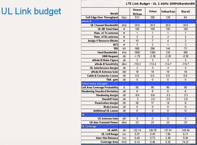
FDD-LTE UL Link budget
FDD-LTE DL Link Budget
Cell radius and areas
FDD-LTE link budget overview
The process of FDD-LTE
network planning

Link budget input and
output

Normal Link budget
requirements

Link budget model

Shannon formula

UL Link budget process

UL link budget
Methodology


Assigned RB number

Number of Resource
Blocks

Modulation & Coding
Scheme
This determines the Modulation Order which in
turn determines the TBS Index.

TBS and MCS

Assign RB number

SINR
- SINR Target depends on:
- eNode-B equipment performance
- Radio conditions (multipath fading profile, mobile speed)
- Receive diversity (2-way by default or optional 4-way)
- Targeted data rate and quality of service
- The Modulation and Coding Scheme
- Max allowed number of HARQ transmissions (Maximum of 4 on UL)
- HARQ BLER target (10% considered by default)
- Derived from link level simulations or better by equipment measurements (lab or on-field measurements)

Assign RB number

Rx receive sensitivity

Thermal Noise
Receiver sensitivity


UL Interference Margin

UL Interference Margin


Four Antenna
configuration way


TMA gain


Shadowing Margin


Hard handover Gain


Penetration loss

Body loss


Propagation model


Different of UL and DL
link budget

DL link budget
Methodology

DL Link budget character

DL link budget approach

- Base on the UL link budget result decide the cell range.
- Base on the decided cell range, get DL path loss at cell edge
- Base on DL path loss and considered DL Tx power and total other gain & loss to get DL signal power at cell edge.
- According Geometry factor at cell edge to get other cell interference
- Base on DL signal power and other cell interference and noise to get DL SINR at cell edge.
- Base on DL SINR at cell edge and the DL bandwidth and available RB number to decide the MCS and TBS, and then, get the DL throughput at cell edge.


DL shadowing Margin


Adjacent Tx
Power load


Geometry factor


SINR


DL Link budget


DL Link budget approach


Limited link

Cell range and inter
site distance

Glossary
- RB: Resource Block
- TBS: Transport Block Size
- MCS: Modulation & Coding Scheme
- SINR: Signal to Interference plus Noise Ratio
- MIMO: Multiple Input Multiple Output
- MAPL: Maximum Allowable Path Loss
- TMA: Tower Amplifier
- BLER: Block Error Ratio
- HARQ: Hybrid automatic repeat request
- SNR: Signal to Noise Ratio
- NF: Noise Figure
- ISD: Inter-station Distance
- CDF: Cumulated Distribution Function
- TTI: Transmission Time Interval
End of Course