

Content:
UE State transition
Signaling flow
Classification of Flows
- In terms of protocol stack, signaling flows can be access layer signaling flows or non-access layer signaling flows.
- In terms of network composition, signaling flows can be categorized as circuit-switched or packet-switched.
- Access layer and non-access layer signaling flows are actually so named from the perspective of protocol stack.
- The flows at the access layer include PLMN selection, cell selection, and radio resource management flows.
- The radio resource management flows are the flows at the RRC layer, including the RRC connection setup flow, flow of the signaling setup between UEs and CNs, RAB setup flow, call release flow, handover flow, and SRNS redirection flow.
UE Working Modes
- There are two basic working modes:
- Idle
- UE stands by without any service. There’s no connection between UE and UTRAN.
- Connected
- UE transferred to the connected mode after accomplishing RRC Connection Setup.
- UE has 4 states under the connected mode:Cell-DCH, Cell-FACH, Cell-PCH, URA-PCH
UE State

UE States Under the Connected Mode
- Cell-DCH
- UE is activated, and in service using its dedicated channels.
- There are dedicated channels in both uplink and downlink.
- UTRAN knows exactly which cell the UE is in.
- Cell-FACH
- UE is activated, but without too much date to transmit, so there’s no need to assign dedicated channels to it.
- Downlink data transmitted in FACH, while uplink in RACH.
- UTRAN knows exactly which cell the UE is in.
- Cell-PCH
- There is no data transmitted in both uplink and downlink.
- UE needs to listen to PICH for paging information.
- UE works in discrete receiving, which saves the power effectively.
- UTRAN knows exactly which cell the UE is in.
- UE needs to do cell update procedure when it passes cells.
- URA-PCH
- There is no data transmitted in both uplink and downlink.
- UE needs to listen to PICH for paging information and receive discretely.
- UTRAN only knows which URA (UTRAN Registration Area) UE exists.
- UE updates its location information only when its URA changes, which further reduces the signaling saves resource.
RRC State Transition (I) Transit from IDLE Mode
- After RRC Connection Setup, UE will transit to CELL_FACH or CELL_DCH.
- CN indicates UE using dedicated channel (CELL_DCH) or common channel (CELL_FACH) according to the service request.
- If there is no service right now, UE will be indicated into PCH mode or release RRC connection back to IDLE mode.

RRC State Transition (II) Transit from CELL_FACH Mode
- UE do not occupy dedicated channels In the mode of CELL_FACH.
- UE receives downlink data through FACH(S-CCPCH).
- UE transmits uplink data through RACH(PRACH).

RRC State Transition (III) Transit from CELL_DCH Mode
- UE transceives uplink and downlink data through dedicated channels (DPDCHs and DPCCHs).
- During the time when there is no data transmitted, CN may indicate UE’s transiting to URA_PCH or CELL_PCH

RRC State Transition (IV) CELL_PCH和URA_PCH
- UE has no activated uplink.
- Paging Information makes UE back to CELL_FACH or CELL_DCH mode.
- In CELL_PCH, UE should transit to CELL_FACH first to finish cell updating, and go back if no service request.
- In URA_PCH, if URA changes, UE also transits to CELL_FACH to finish cell updating first before it goes back to URA_PCH.
- System resource can be saved in these two modes.

Signaling flow
Basic Conception (1)
- RRC (Radio Resource Control)
- provides information transfer service to the NAS (Non Access Stratum).
- responsible for controlling the configuration of UMTS radio interface Layers 1 and 2.
- RRC Connection
- A point to point bi directional connection between the RRC (Radio Resource Control) entities on the UE (User Equipment) and UTRAN (UMTS Terrestrial Radio Access Network).
- The UE requires an RRC connection to access the services of the UMTS network.
Basic Conception (2)
- RAB -Radio Access Bearer
- Identify the service the AS (Access Stratum) provides to the NAS (Non Access Stratum) for transfer of user data between the UE (User Equipment) and the CN (Core Network).
- RB -Radio Bearer
- The service provided by the Layer 2 for the transfer of user data between UE (User Equipment) and UTRAN (UMTS Terrestrial Radio Access Network).
Basic Conception (3)
- RL (Radio Link)
- RL is a logical association between single UE (User Equipment) and a single UTRAN (UMTS Terrestrial Radio Access Network) access point.
- Its physical realization comprises one or more radio bearer transmissions.
- It is possible for a UMTS mobile to have many radio links established, when this occurs the mobile is said to be in a soft handover.


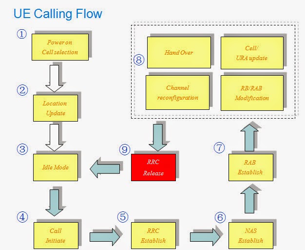
UE Calling Flow

UE Initiate Random Access


Call Setup Flow
- CN initiates a paging message to RNC.
- RNC judges the paging message from the CN and then sends a paging message to the corresponding UE.
- If no RRC connection is available, UE will send a RRC connection setup request message (RRC Connection Request) to RNC.
- RNC determines to set up a RRC connection according to the service request and system resource occupation then sends a RRC connection setup message (RRC Connection Setup) to UE.
- After signaling connection setup, the higher layer of UE (NAS) sends a service request message to CN through a directly transfer message.
- CN sends a RAB assignment message (RAB Assignment Request) to the RNC to allocate resource for UE’s request.


Handover Category
- Intra-system handover
- Softer handover, soft handover, hard handover
- Depending on the Ec/No of CPICH
- Inter-system handover
- Between FDD and TDD
- Handover with different system
- 2G/3G handover
- Compression mode
Softer/Soft Handover
Gain and Costs
- Softer/Soft Handover Gain:
- The optimal fast close loop power control (MS always keep connection with the most powerful cell)
- Seamless handover, without RB interruption
- When MS moves to the edge of the cell, and could not obtain enough signal power, it can obtain Macro diversity from multiple cells
- The UL signaling quality can be improved through obtaining Macro diversity when Node B (Softer HO) and RNC (Soft HO) combine the receiving signal and lower the required Transport power of UE.
- Softer/Soft Handover Costs:
- Additional Rake receiver channel on Node B
- Additional DL channelization code
- Additional DL power
- Additional Rake receiver channel on MS
- Additional transport link between Node B and RNC (RNC internal Soft Handover)
- Additional transport link between S-RNC and D-RNC (Soft handover between RNCs)


SRNC Relocation


DCH-DCH Transport
Channel Reconfiguration

Cell-FACH to Cell-DCH
State Transform

Cell-DCH to Cell-FACH
Transform

RAB Release Flow

RRC Connection Release

Call setup flow (1)

Call setup flow (2)

Call setup flow (3)

Call setup flow (4)

Call setup flow (5)

Call setup flow (6)

Thank You, End of Course!