

Content:
n RAKE
Receiver
n Handover Control
n Compressed Mode
n Admission Control
n Load Control
n Code Resource Allocation
n Capacity Features
Multi-path characteristics of radio channel
n Electromagnetic propagation:
ldirect
radiation、reflection、diffraction
and scattering
n Signal attenuation:
lPath
loss:
Loss
of electromagnetic waves in large scope
of the spread reflects the trend of the received signal in the spreading。
lSlow
fading:Loss
because of being blocked by the building and hill in the propagation path
lFast
fading:Electromagnetic
signals rapidly decline in a few dozens wavelength ranges
n Description of Fast fading distribution
lRayleigh
distribution:non
line-of –sight(NLOS) transmission
lRician
distribution:line-of
–sight(LOS) transmission


RAKE Receiver
n The multi-path signals contain some useful
energy , therefore the UMTS receiver can combine these energy of multi-path
signals to improve the received signal to noise ratio.
n RAKE receiver adopts several correlation
detectors to receive the multi-path signals, and then combines the received
signal energy.
RAKE
Receiver can effectively overcome the multi-path interference, consequently improve the receiving
performance.

Multi-finger receiver
n Traditional receiver
lMulti-path
signals are treated as interference.
lThe
receiving performance will decline because of the Multi-address Interference (MAI).
n Precondition of Multi-finger receiver
lMulti-finger
receiver utilizes the Multi-path Effect.
lMulti-finger
signals can be combined through relative process
lMulti-finger
time delay is larger than 1 chip interval, which is 0.26us=>78m.


Handover Control
What is Handover?
n When UE is moving from the coverage area of
one site to another, or the quality of service is declined by external
interference during a service, the service must be handed over to an idle
channel for sustaining the service.
n Handover is used to guarantee the continuity
of service.
n Handover is a key technology for mobile
networking.


Hard Handover
n During the hard handover procedure, all the
old radio links with the UE are abandoned before new ones are established, so
there must be service interruption during the
HHO.
n Hard handover may occur in the following main
cases
lWhen
the UE is handed over to another UTRAN carrier, or another technology mode.
lWhen
soft handover is not permitted (if O&M constraint)

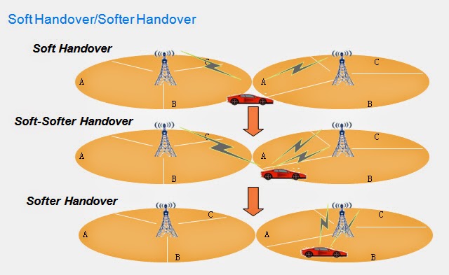
Soft/Softer Handover
n The soft/softer handover allows to migrate from one cell to another without service
interruption or without deleting all old radio links.
n UE can connect to more than one cell simultaneously
and take benefit from the macro-diversity.

UMTS General Handover Trilogy
n Measurement Control
lUTRAN
demands the UE to start measurement through issuing a measurement control message.
n Handover decision
lUTRAN
makes the decision based on the measurement reports from UE. The implementation
of handover decision is various for different vendors. It impacts on the system
performance critically.
n Handover execution
lUTRAN
and UE execute different handover procedure according to the handover command.

General Procedure of Handover Control
n Measuring
n The measurement objects are decided by RNC.
Usually, either Ec/Io or RSCP (Received Signal Code Power) of
P-CPICH channel is used for handover decision.
n RNC adopts Ec/Io measurement, because Ec/Io
embodies both the received signal strength and the interference. The relation
of Ec/Io
and RSCP is shown as follows:
lEc/Io =RSCP/RSSI
n In the above equation,RSSI(Received
Signal Strength Indicator)is measured within the bandwidth of
associated channels
n Filtering
n The measurement results should be filtered
before being reported. Measurement filtering can be regarded as a low pass
filtering procedure. The following equation is
applied for filtering.
n Fn=(1-a)Fn-1+a*Mn
n Variants definition:
lFn:filtered
measurement result;
lFn-1:last
filtered measurement result;
lMn:latest
Ec/Io or RSCP measurement result received from
physical layer;
la =
1/2(k/2), k means the “Filter
coefficient”, which is included in the Measurement Control message. It is
decided by the UTRAN.
lF0 is initialized by the first
measurement result M1.
n Reporting
n Period report triggered handover
lBase
on the filtered measurement result
n Event report triggered handover
lBase
on the event

n Handover
algorithm
lAll
the handover algorithms including soft handover, hard handover and so on are
implemented on the event decision made according to the measurement reports.
n Events defined in 3GPP specifications
lIntra-frequency
events:1A~1F
lInter-frequency
events:2A~2F
lInter-RAT
events:3A~3D
nNote:
RAT is short for “Radio Access Technology”, e.g. UMTS&GSM
Concepts Related to Handover
n Active Set:
lA
set of cells that have established radio links with a certain mobile station.
lUser
information is sent from all these cells.
n Monitored Set:
lA
set of cells that are not in the active set but are monitored according to the
list of adjacent cells assigned by the UTRAN.
n Detected Set:
lA
set of cells that are neither in the active set nor in the monitor set.


Hard Handover
n Hard handover measurement is much more
complex for UE than soft handover measurement.
n Inter-frequency hard handover requires UE to
measure the signal of other frequencies.
n UMTS employs compressed mode technology to
support inter-frequency measurement.
Compressed Mode
Purpose of Compressed Mode
n In order to support inter-frequency and
inter-RAT handover, UE is required to perform inter-frequency and Inter-RAT
measurement periodically.
n The UE with one transceiver does not have the
opportunity to perform inter-frequency measurement during the service period
(especially the voice call) , because the transceiver is busy in transmitting
and receiving the signals all the time.
n Compressed mode can provide idle slot based
transmission time window, which can be used for inter-frequency measurement,
for the UEs in connected state, e.g. CELL_DCH.

Generation of Compressed Mode Frame
n Puncturing
lLower
the symbol rate of physical channel when processing the rate matching procedure
n SF halving
lEmploy
half SF, e.g. employ SF64 to replace SF128
n High layer scheduling
lDecrease
the bit rate from up layer
Admission Control
n The admission control is employed to admit
the access of incoming call. Its general principal is based on the availability and utilization of the system
resources.
n If the system has enough resources such as
load margin, code, and channel element etc. the admission control will accept
the call and allocate resources to it.
Purpose of Admission Control
n When user initiates a call , the admission
control should implement admission or rejection for this service according to
the resource situation.
n The admission control will sustain the system
stability firstly and try the best to satisfy the new calling service’s QoS
request, such as service rate, quality (SIR or BER), and delay etc. basing on
the radio measurement.
n Admission control is the only access entry
for the incoming services, its strategy will directly effect the cell capacity
and stability, e.g. call loss rate, call drop rate.

Admission Control in Uplink
n Different ultimate user numbers
n Different interference threshold under
different ultimate user number conditions
n Different ultimate throughputs


Admission Control Analysis
n The service can be either one-direction or
bi-direction type. For bi-direction service, it is admitted only after both
uplink and downlink are admitted.
n Admission control is the only access entry
for the incoming services, its strategy will directly effect the cell capacity
and stability, e.g. call loss rate, call drop rate.
Load Control


Load Control in Uplink
n Triggers
lRTWP
(Received Total Wide-band Power) value from measurement report exceeds the
uplink overload threshold;
lAdmission
control is triggered when rejecting the access of services with lower priority
due to insufficient load capacity in uplink.
n Methods for decreasing load
lDecrease
the target Eb/No
of service in uplink;
lDecrease
the rate of none real time data service;
lHandover
to GSM system;
lDecrease
the rate of real time service, e.g. voice call;
lRelease
calls.
n Methods for increasing load
lIncrease
the service rate.
Load Control in Downlink
n Triggers
lTCP (Transmitted Carrier Power)
value from measurement report exceeds the downlink overload threshold;
lAdmission control is triggered
when rejecting the access of services with lower priority due to insufficient
load capacity in downlink.
n Methods for decreasing load
lDecrease the downlink target Eb/No
of service in downlink;
lDecrease the rate of none real
time data service;
lHandover to coverage-shared light loaded carrier;
lHandover to GSM system;
lDecrease the rate of real time
service, e.g. voice call;
lRelease calls.
n Methods for increasing load
lIncrease the service rate.
Cell Breathing Effect

Cell Breathing Effect
n With the increase of
activated terminals and the increase of high speed services, interference will
increase.
n The cell coverage area will
shrink.
n Coverage blind spot occurs
n Drop of call will happen at
the edge 
Code Resource Allocation
UMTS Code Resource
n Channelized Code (OVSF code)
lUplink
Channelized Code
lDownlink
Channelized Code
n Scrambling Code
lUplink
Scrambling Code
lDownlink
Scrambling Code
Function of OVSF Code


Why Code Resource Planning?
n The OVSF (Orthogonal Variable Spreading
Factor) code tree is a scarce resource and only one code tree can be used in
each cell. In order to make full use of the capacity, and support as many
connections as possible, it is important to plan and control the usage of
channel code resource.
n Downlink scrambling code allocation should be
planned to avoid the interference between neighboring cells.
n The uplink scrambling codes are sufficient,
but RNC should plan the codes to use for avoiding allocating same code to
different users in inter-RNC handover scenario.
Code Resource Planning
n The
uplink and downlink scrambling code can be planned easily by computer.
n The
uplink channelized code does not need planning, for every UE can use the whole
code tree alone.
n Therefore,
only the downlink channelized code is planned with certain algorithm in RNC.
n Each
cell has one primary scrambling code, which correlates with a channel code
tree. All the users under this cell share this single code tree, so the OVSF
code resource is very limited.
n The
downlink channelized code tree is a typical binary tree with each layer
corresponds to a certain SF ranging from SF4 to SF512.


Channelized Code Characters
n Code allocation restriction :
lThe
code to be allocated must fulfill the condition that its ancestor nodes
including from father node to root node and
offspring nodes in the sub tree are not allocated;
n Code allocation side effect:
lThe
allocated node will block its ancestor nodes and offspring nodes, thus the
blocked nodes will not be available for allocation until being unblocked .

Strategy of Channelized Code Allocation
n Full utilization
lThe
fewer the blocked codes, the higher code tree utilization rate.
n Low Complexity
lShort
code first.
n Allocate codes for common channels and
physical shared channels prior to dedicated channels.
lGuarantee
the code allocation for common physical channels.
n Apply certain optimized strategy to allocate
codes for downlink dedicated physical channels.

Planning of downlink scrambling code

Capacity Features


UMTS Capacity Features
n UMTS capacity feature
lUMTS
capacity is Soft Capacity.
n The Concept of Soft Capacity
lThe
system capacity and communication quality are interconvertible.
lDifferent
services have different capacity.
lDifferent
proportion of services have different capacity for mixed services.
lThe
capacity is also restricted to the allocation of code resource.


Coverage and Capacity
n UMTS performance is determined by such
factors as:
lNumber
of users
lTransmission
rate
lMoving
speed
lWireless
environment
n indoors
n Outdoors
n The radius
of cell depends on such factors as:
lLocal
radio conditions (local interference)
lTraffic
in neighbouring cells (remote interference)
n Cell Radius decrease according to the
Increase of user number

Coverage/capacity VS Data Rate
n Higher data rate needs higher power
n High data rate transmission is only available
nearby the station

Optimization methods
n To overcome Cell Breathing Effect caused by
increased traffic and meet different requirements for capacity and coverage in
different environment, following solutions can be applied:

Factors affects UMTS Capacity
aa

Finish UMTS Key Technologies Course