

Content:
Protocol Structure
LTE System Architecture


Frame Structure(FDD)

Physical Resource Block

Resource Grouping

RB and Bandwidth

Resource Allocation

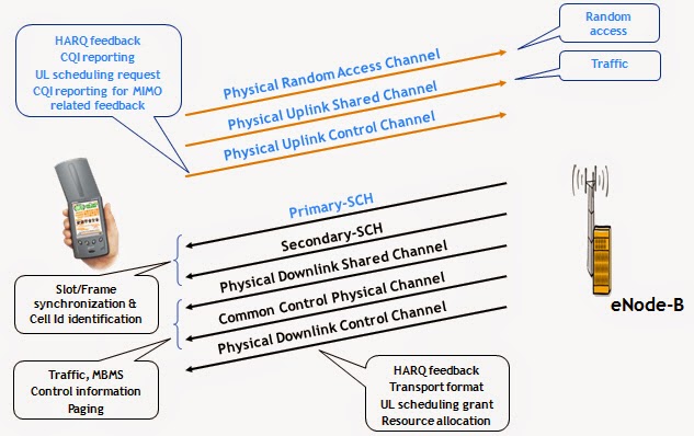
Physical Channel and
Signal

Functions of Each
Channel
PUSCH


PRACH

SCH

PBCH

PBCH bears the BCH-contained system information including downlink system
bandwidth, system frame number (SFN), PHICH duration, and resource-size
indication information.
Each
No.0 sub-frame has four PBCH signals of OFDM symbols.
PCFICH

PCFICH
and E-Node B are transmitted in each sub-frame, informing UE of the OFDM
symbols that PDCCH occupies in a sub-frame. The OFDM symbols are indicated by
CFI which can be valued as 1, 2, 3, 4 (4 is reserved).
PHICH

•PHICH sends NAK/ACK responding information for the
uplink sent signal when bearing E-Node B.
•Two PHICH durations in one sub-frame:1.
short PHICH 2. long PHICH; This duration
is indicated by 1 bit in PBCH.
•In each downlink sub-frame, PHICH needs to be sent.
Multiple PHICH groups can be sent at the same time. Define one PHICH group to be mapped from multiple ones to a PHICH in
the same RE.
PDCCH (physical downlink
control channel)

•All the information can group multiple types of control information (DCI) format which is mapped to the first n (n<=4) OFDM symbols in each sub-frame. The value of n is indicated by CFI in the PCFICH channel.
•In a sub-frame, we can transmit multiple PDCCHs. One UE can monitor one group of PDCCH. Each PDCCH is sent in one or more control channel elements (CCE) to achieve the different PDCH encoding rates by integrating various numbers of CCEs.
•PDCCH supports 4 types of physical-layer formats which occupy one, two, four, and eight CCEs respectively.
PDSCH

Physical-layer process –
Cell Search

Physical-layer process
–Power Control

Open-loop power control: Decide a starting emission power of UE emission power as the basis for closed-loop control adjustment.
Closed-loop power control: eNode B measures SINR of PUCCH/PUSCH/SRS signal, then compares SINR with SINRtarge to determine the TPC command (what’s informed is power step size.), finally informs UE through PDCCH to determine the emission power of uplink sent signal on the corresponding sub-frame.
Outer-loop power control: According to the change of environment, adjust the channel of received signal SINR target
Inner-loop power control: To solve the near-far effect and loss, make the received signal maintain fixed SINR
Physical-layer process
–Random Access

Random
access process can be used in the following situations:
Access at RRC_IDLE status
Access when the wireless link fault occurs
Access in changeover
Access at RRC_Connected status
When there are downlink data (eg. The uplink is at non-synchronization status.)
When there are uplink data (eg. The uplink is at non-synchronization status or no
PUCCH resource can be used for scheduling request.)
Random access based on competitiveness
Used in the five mentioned situations
UE selects a preamble sequence
randomly in the available preamble set in a competitive way.
Possible collision: two UEs use the
same preamble sequence.
Perform the synchronization process
through four steps. The fourth step is used to solve the collision.
Random access based on non-competitiveness
In changeover or when the downlink
data arrive
The BS allocates a preamble sequence.
Perform the synchronization through
three steps without solving the collision.
Random Access Process
(Based on Non-competitiveness)

1.
eNB send non-contention
Random Access Preamble to UE
2.
UE send Random Access Preamble through
RACH
3.
The eNB send Random Access Response through DL-SCH
Random Access Process
(Based on Competitiveness)

UE sends Msg1 and Msg1 passes PRACH, (RACH-》PRACH)
eNB measures the distance between UE and BS according to the received preamble, and generates timing adjustment quantity.
Step2:
eNB sends Msg2 and Msg2 passes PDSCH (DL-SCH-》PDSCH)
The location is indicated by PDCCH, no HARQ.
Msg2 is the grant of Msg4. If UE fails to receive the RA respondence in a time window, this RA process is terminated; otherwise it goes to step3.
Step3:
UE sends Msg3 and passes PUSCH (UL-SCH-》PUSCH), HARQ
eNB detects Msg3 and generates ACK/NACK.
Step4:
eNB sends Msg4 for collision detection, HARQ
UE finds that the UE of its own NAS-layer ID is sending ACK.
Introduction to MAC

•Resides on layer 2 of LTE wireless protocols (L2;L2
also includes RLC and PDCP)
•Used to allocate the wireless resources (time, frequency
(number of RBs and location), number of emission layers, number of antenne, and emission power) to users
•Resides in both E-Node B
and UE, but has different functions.
The Overview of MAC
Structure

MAC Entities
E-UTRA
defines two MAC entities; one in the UE and one in the E-UTRAN. These MAC
entities handle the following transport channels:
- Broadcast Channel (BCH);
- Downlink Shared Channel (DL-SCH);
- Paging Channel (PCH);
- Uplink Shared Channel (UL-SCH);
- Random Access Channel(s) (RACH).
The
exact functions performed by the MAC entities are different in the UE from
those performed in the E-UTRAN.
Figure
4.2.1.1 illustrates one possible structure for the UE side MAC entity, and it
should not restrict implementation.
Mapping between Logical
CHs & Transport CHs

The
MAC sublayer operates on the channels defined
below; transport channels are SAPs between MAC and Layer 1, logical channels
are SAPs between MAC and RLC.
Functions of MAC sub
layer

At UE side
Mapping between the logic channel and transmission channel
MAC SDUs multiplexing/de-multiplexing <-> MAC PDU
HARQ
Buffer status report (BSR)
At eNode-B side
Mapping between the logic channel and transmission channel
MAC SDUs multiplexing/de-multiplexing <-> MAC PDU
HARQ
Scheduling among UE of different priorities (dynamic scheduling, semi-persistent scheduling)
Selecting transmission format (MCS)
Priority processing among different logic channels in the same UE
Services related to MAC sub layer

Key Technology at MAC
Layer- Fast Scheduling
- LTE TDD downlink: 1ms - 4ms (related with uplink/downlink configuration)
- LTE TDD uplink: 1ms - 10ms (related with uplink/downlink configuration) UMB: 1ms.
- WiMAX TDD: 5ms.
- WCDMA HSDPA: 2ms.
- CDMA 2000 1x EV-DO: 1.667ms.
Key Technology at MAC
Layer- Fast Scheduling-Classification


At
UE side
Mapping between the logic channel and transmission
channel
MAC SDUs multiplexing/de-multiplexing <-> MAC PDU
HARQ
Buffer status report (BSR)
At
eNode-B side
Mapping between the logic channel and transmission
channel
MAC SDUs multiplexing/de-multiplexing <-> MAC PDU
HARQ
Scheduling among UE of different priorities (dynamic
scheduling, semi-persistent scheduling)
Selecting transmission format (MCS)
Priority processing among different logic channels in
the same UE

4.3.1 Services provided
to upper layers
The
following services are provided by RLC to upper layer (i.e. RRC or PDCP):
- TM data transfer;
- UM data transfer;
- AM data transfer, including indication of
successful delivery of upper layers PDUs.
4.3.2 Services expected
from lower layers
The
following services are expected by RLC from lower layer (i.e. MAC):
- data transfer;
- notification of a transmission opportunity,
together with the total size of the RLC PDU(s) to be transmitted in the
transmission opportunity.

An
RLC entity in transparent mode can send/receive RLC PDU through the logic
channels, such as BCCH, DL/UL CCCH and PCCH

An
RLC entity in non-confirmation mode can send/receive RLC PDU through the logic
channels, such as DL/UL DCCH, DL/UL DTCH, MCCH/MTCH.
Compared
with 3G, the UM mode does not support the encryption/decryption function which
is processed in PDCP.

An
RLC entity in confirmation mode can send/receive RLC PDU through the logic
channels, such as DL/UL DCCH, DL/UL DTCH

SRB is used for the transmission of RRC and NAS messages
PDCP serves SRB and DRB mapped on the logic channels
DTCH and DCCH. The functions provides on DTCH and DCCH are as follows:
DTCH channel
PDCP packet transmission
SN sequence number maintenance
Header compression and decompression
of IP data flow
Encryption and decryption
Resorting of lower-layer PDU data in
switch-over
DCCH channel
PDCP packet transmission
SN sequence number maintenance
Integrity protection
Encryption and decryption

The protocol structure of each layer of E-UTRAN is designed according to a universal protocol model, which makes the between-layer and between-plane logically independent and facilitates the modification of protocol stacks and protocol planes. For the protocol plane, the protocol structure involves two layers: radio network layer (RNL) and transmission network layer (TNL).
PDCP is a functional entity. It separates the transmission technology on TNL from the air-interface processing technology on E-UTRAN. Other layers above TNL are not related with the air interface.
PDCP maps the upper-layer protocol characteristics to the lower-layer air interface protocol characteristics and thus enables the LTE protocol to bear IP packets between UE and E-Node B through transparent transmission provides for the upper layer.

At both receiving side and sending side, resides a peer protocol entity, which is responsible for the PDCP packets’ encapsulation and resolution. One UE corresponds to multiple RBs (radio bearers); while each RB corresponds to one PDCP entity.
Each PDCP entity is associated with one or two (one corresponds to one direction.) RLC entity, which is determined by RB characteristics (uni-direction or bi-direction) and the RLC transmission mode. The property of PDCP entity is configured by the upper-layer protocol RRC on the control plane.

PDCP
provides its services to the RRC and user plane upper layers at the UE or to
the relay at the evolved Node B (eNB).
The following services are provided by PDCP to upper layers:
- transfer of user plane data;
- transfer of control plane data;
- header compression;
- ciphering;
- integrity protection.
Services expected from lower layers
For
a detailed description of the following functions see [5].
- acknowledged data transfer service, including
indication of successful delivery of PDCP PDUs;
- unacknowledged data transfer service;
- in-sequence delivery, except at
re-establishment of lower layers;
- duplicate discarding, except at
re-establishment of lower layers.

The RRC protocol includes the following main functions:
- Broadcast of system information:
- Including NAS common information;
- Information applicable for UEs in RRC_IDLE, e.g. cell (re-)selection parameters, neighbouring cell information and information (also) applicable for UEs in RRC_CONNECTED, e.g. common channel configuration information.
- Including ETWS notification, CMAS notification;
- RRC connection control:
- Paging;
- Establishment/ modification/ release of RRC connection, including e.g. assignment/ modification of UE identity (C-RNTI), establishment/ modification/ release of SRB1 and SRB2, access class barring;
- Initial security activation, i.e. initial configuration of AS integrity protection (SRBs) and AS ciphering (SRBs, DRBs);
- RRC connection mobility including e.g. intra-frequency and inter-frequency handover, associated security handling, i.e. key/ algorithm change, specification of RRC context information transferred between network nodes;
- Establishment/ modification/ release of RBs carrying user data (DRBs);
- Radio configuration control including e.g. assignment/ modification of ARQ configuration, HARQ configuration, DRX configuration;
- QoS control including assignment/ modification of semi-persistent scheduling (SPS) configuration information for DL and UL, assignment/ modification of parameters for UL rate control in the UE, i.e. allocation of a priority and a prioritised bit rate (PBR) for each RB;
- Recovery from radio link failure;
- Inter-RAT mobility including e.g. security activation, transfer of RRC context information;
- Measurement configuration and reporting:
- Establishment/ modification/ release of measurements (e.g. intra-frequency, inter-frequency and inter- RAT measurements);
- Setup and release of measurement gaps;
- Measurement reporting;
- Other functions including e.g. transfer of dedicated NAS information and non-3GPP dedicated information, transfer of UE radio access capability information, support for E-UTRAN sharing (multiple PLMN identities);
- Generic protocol error handling;
- Support of self-configuration and self-optimisation;

Triggering
cause
(RRC
connection request, RRC connection reconstruction, RAB assignment, measurement
reports, configuration changes ...)
Signaling
/ Service acceptable, handover Algorithm Are required the Judgment / Access
mechanism。The results of
Judgment / Access

The purpose of paging is to notify incoming call , the change of
system information or ETWS information to UE which is in IDLE or CONNECTED
state.
The paging information is provided to upper layers,
which in response may initiate RRC connection establishment, e.g. to receive an
incoming call.
E-UTRAN initiates the paging procedure by transmitting
the Paging message . One paging message can identify numbers of UE.

The
process used to establish an RRC connection, including conflict resolution and
SRB1 establishment. Also sent the initial NAS message from UE to network.

The
purpose of this procedure is to modify an RRC connection, e.g. to establish/
modify/ release RBs, to perform handover, to setup/ modify/ release
measurements. As part of the procedure, NAS dedicated information may be
transferred from E-UTRAN to the UE.
E-UTRAN may initiate the RRC connection reconfiguration
procedure to a UE in RRC_CONNECTED. E-UTRAN applies the procedure as follows:
- the mobilityControlInfo is included only when AS-security
has been activated, and SRB2 with at least one DRB are setup and not suspended;
- the
establishment of RBs (other than SRB1, that is established during RRC
connection establishment) is included only when AS security has been activated;

The
purpose of this procedure is to re-establish the RRC connection, which involves
the resumption of SRB1 operation and the re-activation of security.
A
UE in RRC_CONNECTED, for which security has been activated, may initiate the
procedure in order to continue the RRC connection. The connection
re-establishment succeeds only if the concerned cell is prepared i.e. has a
valid UE context. In case E-UTRAN accepts the re-establishment, SRB1 operation
resumes while the operation of other radio bearers remains suspended. If AS
security has not been activated, the UE does not initiate the procedure but
instead moves to RRC_IDLE directly.
E-UTRAN applies the procedure as follows:
-to reconfigure SRB1 and to resume data transfer only
for this RB;
-to re-activate AS security without
changing algorithms.
The UE shall only initiate the procedure when AS
security has been activated. The UE initiates the procedure when one of the
following conditions is met:
1> upon
detecting radio link failure,
1> upon
handover failure,
1> upon
mobility from E-UTRA failure,
1> upon
integrity check failure indication from lower layers; or
1> upon an RRC
connection reconfiguration failure,

The
purpose of this procedure is to release the RRC connection, which includes the
release of the established radio bearers as well as all radio resources.


- When eNB need the measurement from UE, eNB will send the measurement control to UE.
- UE will report the measurement according by the Measurement control, when the measurement results meet the conditions in ReportConfig, UE report it.
- When receive Measurement Report, eNB will judge and trigger handover or SON-related operations.
End of Course