

Content
UMTS Paging
UMTS Random Access
UMTS RRC Connection Setup and Release
Access Failed Case
System Broadcasting
- The system information broadcasted over the BCH channel mainly includes the following contents:
- Public Land Mobile Network (PLMN) ID, location area (LA), route area (RA)
- Information on the timers and counters related to the Radio Resource Control (RRC) connections
- Configuration information of the UTRAN registration area (URA)
- Cell selection and reselection parameters
- Parameters for configuring the common channels, such as FACH, PCH, and RACH
- Information on the uplink interference related to the auxiliary power control
- UE measurement control message over the idle or common channel
- Parameters of the adjacent cell
System information
- Master information block (MIB)
- Schedule block (SB)
- System information block (SIB)
- SIB1, SIB2, SIB3, SIB5, SIB7, SIB11, SIB11bis, SIB18.

Scheduling levels of the
SIBS

SIB Block

System broadcasting


SIB3/SIB4


SIB7
- SIB7 is the system information block that is updated periodically. The timer of SIB7 is calculated as follows:
- Expiration timer = MAX(32,SIB_REP * ExpirationTimeFactor)
- SIB_REP is the transmission interval of SIB7 and is obtained at the time of broadcast scheduling; ExpirationTimeFactor is the timeout factor of SIB7 and is set to 2 invariably.
- SIB7 contains the parameters needed in the calculation of the PRACH preamble power.

SIB11/SIB12
SIB18

SIB11bis

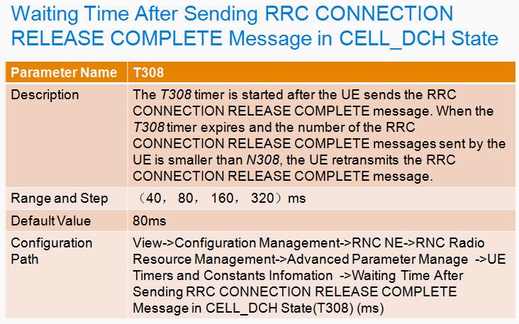
Waiting Time After UE
Sending RRC CONNECTION SETUP REQUEST Message

Maximum Number of
Retransmissions of the RRC CONNECTION REQUEST Message


Paging Flow

PAGING TYPE 1
Page Indicator
- The PCH channel has a corresponding PICH physical channel. The page indicator (PI) is transmitted over the PICH channel, with each PI corresponding to a group of UEs. The following lists the formula for calculating the PI:
- PI = DRX Index mod Np
- Where:
- DRX Index = IMSI div 8192
- Np = the number of PIs included in a PICH frame.
Page Indicator

Paging Occasion
For saving power, the UE in the Idle or PCH state monitors the PICH channel in the Discontinuous Reception (DRX) mode. In the DRX mode, the UE monitors the PI once every DRX period. That is, each UE has its own paging occasion (PO). The UE monitors each PICH frame in the corresponding SFN and finds its own PI in the frame according to the calculated PI. Therefore, the RNC fills in the PI in the message transmitted over the PICH channel according to the paging occasion of the UE. DRX period = 2k frames

DRX cycle length coefficient
- When the UE is in the Idle mode, the RNC calculates K in the DRX period according to Kcs, Kps, and DRX Cycle Length Coefficient in the paging message from the CN.
- For paging messages from the CS domain, K = Min(Kcs,Kps)
- For paging messages from the PS domain, if the CN adds DRX Cycle Length Coefficient to the paging message, K = Min (Kcs, Kps, DRX Cycle Length Coefficient).If the CN does not add DRX Cycle Length Coefficient to the paging message, K = Min(Kcs,Kps).
- When the UE is in the PCH state, the RNC calculates K in the DRX period according to Kcs, Kps, KUtran, and DRX Cycle Length Coefficient in the paging message from the CN.
- For paging messages from the CS domain, K = Min(Kcs,KUtran)
- For paging messages from the PS domain, if the CN adds DRX Cycle Length Coefficient to the paging message, K = Min (Kps, KUtran, DRX Cycle Length Coefficient). If the CN does not add DRX Cycle Length Coefficient to the paging message, K = Min(Kps,KUtran).

PAGING TYPE 2
When the UE is in the DCH or FACH state, the UTRAN initiates the paging process and sends a paging message of PAGING TYPE 2 over the DCCH channel. The UTRAN configures paging cause in the message. After the UE in the DCH or FACH state receives the message of PAGING TYPE 2, it starts the paging reception process and reports paging cause and paging record type identifier to the upper layer.


UMTS Random Access
PRACH Structure

Preamble Part
The preamble part of PRACH is 4096 chips long. It is obtained by repeating the 16-chip signature for 256 times and then processed with RPACH preamble scrambling.
Message Part

Channelized code of PRACH message part
- The spectrum spreading code used by the control part of PRACH is cc = Cch,256,m. where m = 16×s + 15.
- The spectrum spreading code used by the data part of PRACH is cd =Cch,SF,m. where SF=256, 128, 64, 32 are the spectrum spreading factor of the data part, m = SF×s/16.
- s(0 less than s bigger than 15) is the serial number of the signature used by the PRACH preamble part among all 16 PRACH preamble signatures.
- Number of bits carried in PRACH message vs spectrum spreading factor:

Random Access Process of Physical Layer
- Select an available access slot
- Select a signature
- Set the preamble retransmission counter
- The UE calculates the initial transmit power of preamble
- If the UE fails to receive, in the DL access slot corresponding to the slot that sends the UL access preamble, the positive or negative response (AI = +1 nor –1) corresponding to the selected signature on AICH, Increase the transmit power of random access preamble by one PRStep.
- If the UE receives, in the DL access slot corresponding to the slot that sends the UL access preamble, the positive response corresponding to the selected signature on AICH, then the UE sends the message part of random access.

RACH Sub-channel

PRACH/AICH timing relation


UMTS RRC Connection Setup and Release
RRC Connection Setup


RRC Connection Setup

Establishing a RRC Connection over a Dedicated Transport channel
- When receiving the RRC CONNECTION REQUEST message from a UE, the RNC specifies the channel over which the RRC connection is to be established according to the parameter InitRrcOnDch.
- If the parameter InitRrcOnDch is set to 0 (Forced to DCH and Using Normal Speed Signaling) or 1 (Forced to DCH and Using 13.6Kbps signaling), or 5(Forced to DCH and using 27.2Kbps), the RNC establishes the RRC connection over the DCH channel.
- If the parameter InitRrcOnDch is set to 3 (Not Forced, Using 3.4Kbps Signaling on Cell-DCH State) or 4 (Not Forced, Using 13.6kbps Signaling on Cell-DCH State), or 6(Not Forced, Using 27.2Kbps Signaling on Cell-DCH State), the RNC selects to establish the RRC connection over the DCH according to the establishment cause in the RRC CONNECTION REQUEST message.
- When receiving the RRC CONNECTION REQUEST message from a UE, the RNC specifies the channel over which the RRC connection is to be established according to the parameter InitRrcOnDch.
- If the parameter InitRrcOnDch is set to 2 (Forced to FACH), the RNC establishes the RRC connection over the FACH channel.
- If the parameter InitRrcOnDch is set to 3 , 4, or 6, the RNC establishes the RRC connection according to the establishment cause. If there is only a signaling process, instead of setting up services(for example, the value of establishment cause is registration ), RNC will select common channel to bear signaling.
If the radio link setup fails, the RNC sends the RRC CONNECTION REJECT message to the UE and fills in Wait Time in the message. The parameter Wait Time specifies the duration (from the reception of the RRC CONNECTION REJECT message to the time of sending access request) during which the UE has to wait.
Failure to Receive RRC Connection Setup Response From UE
If RNC havn’t received RRC CONNECTION SETUP COMPLETE for waiting 5 seconds from the first transmitting of RRC CONNECTION SETUP, the RRC connection setup fails. The UE is still in idle mode.
Releasing the RRC Connection
- The connection carrying services data or NAS signaling is released normally.
- The Node B detects radio link failure.
- The RNC monitors the RLC connection failure.
- The UE in the DCH or FACH state sends CELL UPDATE message. The value of AM_RLC error indication is true.
- The UE in the FACH state sends the CELL UPDATE message to the RNC. The cause is Radio link failure or RLC unrecoverable error.

RRC connection release flow


Access Failed Case
Description
Customer complained that it was difficult to access the network in office, and it was too long to wait.
Analysis
- The drive test shows that the receiving level of UE is normal. Besides, there is no alarm related to hardware.
- The Performance Management System(PMS) software of NodeB shows the statistics of accessing. A large amount of rejection of access is found, which occupied the demodulation resource, causing the long time to wait for a call connection.

- Preamble_Initial_Power = Primary CPICH DL TX power – CPICH_RSCP + UL interference + Constant Value
- “Primary CPICH DL TX power – CPICH_RSCP” is the Pathloss of downlink.

Use the signaling trace tools of OMCR, RNC didn’t receive the “RRC Connection Request” message. Use the BMC TRACE, find “Rach CRC Error”.So, we make a conclusion that the Preamble Threshold is too big which result in the message transmit power is very low, and NodeB cannot receive the message.
Solution
- Solution
- Change the Preamble Threshold:-24dBà-21dB
- Constant Value:-21dBà-18dB
- Result
- Test again, make a call 120 times, all the calls are successful.

End of Course