
A communication entity is likely to have two logical planes, signaling and transmission. It depends on standards/specification to decide as how it would be taken care - whether use same communication link for signaling and transmission or use different ones or may be some combinations of it. During earlier analog world, the signaling and transmission use to be over same links. Even today, the (traditional public telephone network) landline phones that we use fall in the same category.
Typically this phone will be set up in such a way that when we pick up the receiver, a simple electrical circuit will be completed, signaling that I am going to dial now. Dial tone will be sent over this circuit/line. And when you dial a digit, your phone will send certain frequency (or combination of certain frequencies) over same circuit/line. The device at the other end will detect this waveform signal and know the dialled digit. Once called phone start ringing, the same line will be used for ringing sound. And of course, when called party answers the call, voice will be transmitted over same line. So here we use same line for both signaling and transmission.
Before CCS6/SS7, on network side too, signaling and transmission used to be on the same link which would be reserved during setup. Refer the diagram below.
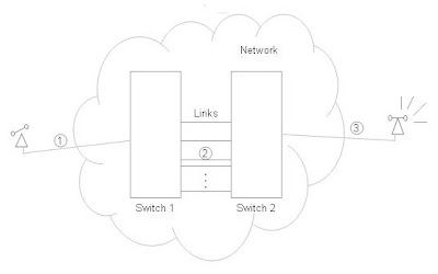
Even though the other phone is ringing, the communication links are reserved in network. This is inefficient - 1) If called party do not answer till timeout, reserved links are not used, 2) Links reserved in network will not carry any transmission information (i.e. voice for voice call) during setup and so underused. Note that these links are bidirectional. 3)Depending on number of telephone switches connecting in-between (STD call will go thru more switches than local call, and ISD call more than that for STD call), there will be more wastage of communication links.
Concept of translation or routing: When you make a call, the number gets "translated" at switch. Let us take an example.
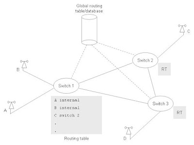
When person A makes a call to B, Switch1 from its translation/routing table decides that B is on the same switch and it don't have to route the call further. But when A calls C, Switch1 routes to Switch2 as per routing table.
Now let's say person A activates call forward and configures that call to be forwarded to D. Switch1 updates routing table accordingly. This call forward is known only to Switch1. If C calls A, Switch2 routes the call to Switch1. As call forward active on A, Switch1 routes the call to Switch3. So instead of only one trunk between Switch2 and Switch3 being used, two trunks are being used (between 1 & 2 and 1 & 3).
All switches maintain their own routing tables. As number of users grow, technologies improve, new switches will be added into the network, old ones will be replaced, this all would require updation of routing tables in all of the switches.
It is apparent that there is a need for switches to interact with each other for purposes other than only call setup. As an enhancement, we can as well have global routing table for not found or special numbers. This table can be made accessible to all switches over simple signaling links.
So it seems we need to separate signaling from transmission.
Common Channel Signaling 6(CCS6), which evolved into Signaling System 7(SS7), recommended to have separate signaling links and transmission links. That in a way mean, we can have signaling network separate from transmission network with transmission network obeying orders from signaling network.
Let us see how we can do it, refer the diagram below.
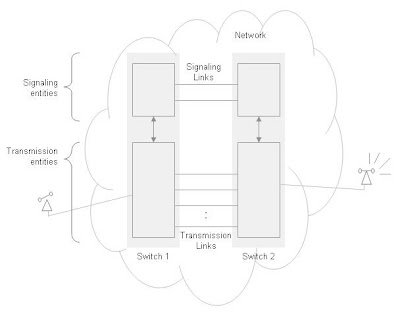
Now we do not have inefficiency related to transmission link. Transmission links will be required at later stage in call setup, making it more efficient. Both directions of link need not be reserved. Also as signaling information is smaller amount of data compared to transmission data, signaling link can be time shared between number of connections. That adds up to saving.
Call forward scenario can be handled in organised and better way.
Consider a popular example of pizza number. We would like to keep the pizza number same throughout city, state and may be even country, when user dial a pizza number, the call should go to nearest pizza delivery center. Signaling network - independent of transmission network - can intelligently convert the dialled number to nearest pizza center number using global routing table accessible in signaling network and instruct transmission network to complete the call accordingly.
CCS6/SS7 allows us to think of and implement these enhanced features. Today's GSM network also use the same concept. In fact GSM network use SS7 as signaling and transmission backbone.
Ever wondered when you are going around the city, how your GSM mobile network finds your mobile ? Try to catch the similarity with above pizza example. Your mobile talks (i.e. signals) to network that "I am here" as and when location changes. Network keep updating that in its "location register". Most of these location update signaling (and number of other GSM signaling) uses underlying SS7 network's signaling capabilities.
SS7 protocol was defined by ITU-T in Q.700 series (in 1980), national variants defined by ANSI (USA), ETSI (Europe), RRC (China), and TTC(Japan).
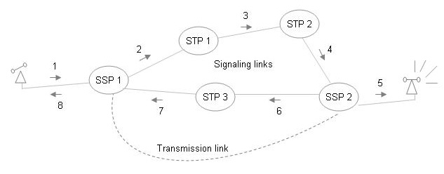
Below is network proposed by SS7.
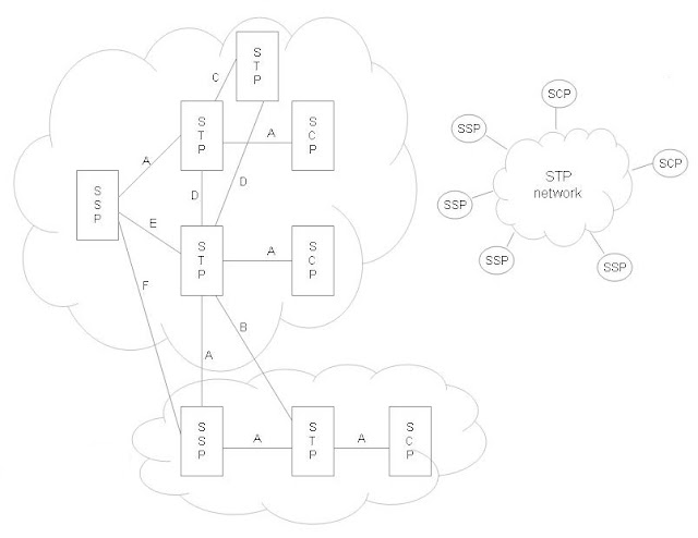
SSPs (Service Switchin Points) are basically telecom switches, in charge of call setup and tear down.
STPs (Signal Transfer Points) provide network layer functions - major function being routing messages to make sure message reach intended entity.
SCP (Service Control Points) provide database functions.
1st diagram shows two networks with above SS7 points and their interfaces. 2nd diagram is simplified to show that STP form a backbone for network. It suggest that SSPs can talk to each other transparently with the help of STPs. These STPs are organised in such a way that there are sufficient number of paths from one SSP/SCP to another SSP/SCP.
All above SS7 points are recognised by (unique) physical address called "Point code".
Let us take an example of call setup.
A makes a call to B. SSP1 from its routing table finds out that B is located on SSP2. So it sends a setup message over a signaling link to STP1, mentioning Point Code of SSP2 as destination and its own as origination. STP1 does not have direct path to SSP2, so it routes the message to STP2. STP2 finding point code of SSP2, sends the message to SSP2. SSP2 notes that the called number is of B and it is present with it. So SSP2 triggers ringing to B (If SSP2 do not have B, it will route the call further to next level of SSP (through STP network) and will wait for reply from it.). At the same time, SSP2 sends (sort of) acknowldgement message back, mentioning SSP1's point code. Now this message can go through the same path or different path than the message sent by SSP1. SSP1, upon receiving message from SSP2, sends ringing tone to A. At this or later time, one way or two way transmission link from SSP1 and SSP2may be reserved. Once B answers or times out, STP network will be used to next set of signaling exchange (call answered or tear down respectively).
Now consider a call to 800 number. This being a special number, SSP1 may not have information of where it is to be routed. In this case, it needs to query SCP for the routing information (basically a routable number that can used to locate the destination SSP). SCP contain multiple number of databases. SSP1 may or may not know the point code of SCP and the database that is to be queried. If SSP1 knows this information, it will send query message to SCP (via STPs). If SSP1 do not know point code and/or database of SCP, it will still send query by mentioning the 800 number (and leaving database/point code information not specified). STP network will insert this information and will route the message to appropriate SCP. SCP will send back the routing information to SSP1. SSP1 will then go ahead with the call as usual.
MTP3
Below is SS7 layers diagram.
 | Umbrella specification for SS7 is Q.700. MTP (Message Transfer Part) - Q.701 - Q.709 SCCP (Signaling Connection Control Part) Q.711 - Q.716 TUP (Telephone User Part) - Q.721 - Q.725 ISUP (ISDN User Part) - Q.761 - Q.766 TCAP (Transaction Capabilities Application Part) - Q.771 - Q.775 Test - Q.780 - Q.783 |
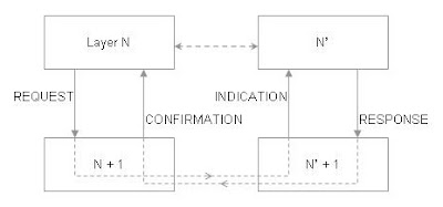
SS7 recommend Primitive (messages) based approach for interlayer communication as shown below. 3GPP (GSM) standard follow the same practice.
MTP (Message Transfer Part)
MTP 1 correspond to OSI Physical layer. SS7 do not specify the physical interface to be used, but due to existing deployment, DS0A or V.35 interface. Both these interfaces provide 54/64 kpbs data rate. In practice, high speed links are used DS1/DS3. These link may get migrated to ATM and then SONET. This migration will also require replacing MTP 1, and MTP 2, and part of MTP 3 with an adaptation layer.
MTP 2 correspond to OSI Data link layer. "Reliable" transfer from "node to node" is aim here. To do this, it incorporates Link management, Error detection and checking techniques (like CRC - Cyclic Redundancy Check), Acknowledgment techniques (Sequence numbering). Link management is about bringing the link to service, detecting failed links etc. Error detection and checking techniques typically puts additional data to transmission data before transmitting. The additional data is calculated in such a way from transmission data that it would be possible to detect the error and may be possible to correct it. Sequence numbering allows to make sure that the data has been received by the receiver. It gives sequence number to the packet of data. And receiver acknowledges these sequence numbers. If sender do not receive acknowledgment for some sequence numbers, sender does the retransmission.
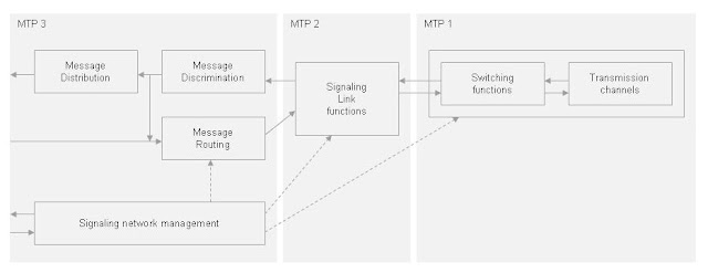
MTP 3 is layer 3 (handling network layer functions of OSI model) of SS7 stack. As mentioned point code is used by MTP 3 for routing. The point code is be provided by ISUP, SCCP, or TUP in routing label (part of message passed to MTP 3). Once MTP 3 receives a message from MTP 2, it checks if it is intended for the current entity with the help of point code. If so, it passes the message to upper layer removing MTP related elements from message. Otherwise, the message is routed to next point (SS7 entity) based on routing tables.
Below is block diagram of MTP functions given by Q.701.
Below is a diagram showing MTP Signaling unit (message).
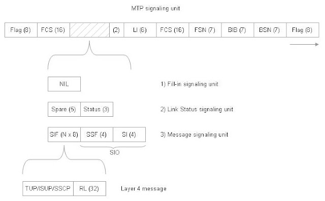
SU - Signaliing Unit
FCS - Frame Check Sequence (Error correction)
LI - Length Indicator (indicate type of SU)
FIB - Forward Indicator Bit
FSN - Forward Sequence Number
BIB - Backward Indicator Bit
BSN - Backward Sequence Number
SIF - Signaling Information Field (International or National and Priority(2 bits) )
RL - Routing Label (Contain Originating Point Code, Destination Pointe Code, etc.)
SIO - Signaling Information Octet
SSF - SubService Field
SI - Service Indicator (indicate (service) whether ISUP, SCCP, TUP etc.)
MTP primitives are
MTP-TRANSFER (Req/Ind),
MTP-PAUSE (Ind),
MTP-RESUME (Ind),
MTP-STATUS (Ind)
MTP-PAUSE (Ind),
MTP-RESUME (Ind),
MTP-STATUS (Ind)
SCCP:
Signaling Connection Control Part (SCCP) [Under SS7]
MTP provide routing based on point code, but when the message is to be addressed based on address other than point code, MTP will not able to do it. SCCP comes into picture there. SCCP does the "global title" translation. In addition, with the help of "sub-system number", SCCP identifies the user of SCCP within the entity. Let's have a look at the pizza (800) number example (SS7 -1) for more clarity.
SSP would like to know the actual/routable number corresponding to (global) pizza number dialed. In this case, SSP can inject a database query into STP network without knowing the SCP point code and database that is to be queried. SCCP on in-between STPs will insert correct SCP point code/sub-system number and so the message will be routed to appropriate SCP. This is known as "global title translation".
SCCP allow routing based on (one, two or all) GT, SSN, and Point Code. Examples of GT are 800 number (US public switched telephone network), Mobile number (GSM network). Example values of SSN are SCCP management, HLR, VLR, MSC, MAP (last 4 related to GSM network).
MTP provide node-to-node connectivity, SCCP can provide origination node-to-destination node connectivity. SCCP provide both connection-oriented (CO) and connection-less (CL) services. Let us be clear about difference between these two services. In CO, SCCP user will (explicitly) create a connection (with primitive N-CONNECT-REQUEST) giving Called Address. This "connection" - identified by Connection Identification parameter - will be used by SCCP user for data transfer (using primitive N-DATA-REQUEST). In CL, SCCP user do not have to request a connection and can directly send data (using primitive N-UNITDATA-REQUEST).
SCCP provide following services - known as protocol class:
Class 0 - Basic CL
Class 1 - Sequenced CL
Class 2 - Basic CO
Class 3 - Flow control CO
Class 4 - Class 3 + Error recovery CO
Class 1 - Sequenced CL
Class 2 - Basic CO
Class 3 - Flow control CO
Class 4 - Class 3 + Error recovery CO
SCCP CL services are popular and mostly used. Popular usage is for TCAP queries - used for Database queries (for 800 number calling, Local Number Portability) and MAP (Mobile Application Part) transactions in GSM networks. BSSAP layer - part of "A" interface between Access network (BSC node) and Core network (MSC node) - in GSM uses SCCP CO services.
In case the message (SIF) exceed MTP SDU limit, SCCP segment the message and peer SCCP does the reassembly.
Below is a diagram showing internal architecture of SCCP.
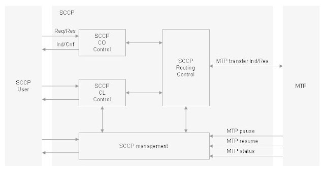
SCMG handles signaling route management (similar to MTP link functions but between end-to-end point), Flow control. It may even restart the transmission. SCMG function are as per request protocol class.
| Flow Control Flow Control is one of the important concepts in telecom/networking world. As the name suggests, Flow Control controls the in-flow and out-flow of data. A simple example would be two nodes doing data transfer, but support different transfer rate. Node supporting low data rate may not be able to process (consume) all the incoming data and its incoming data "queue" is likely to get full. A simple way to avoid this scenario would be: receiving node may signal to transmitting node to "suspend" the transmission and then signal to "resume" once its ready. This may be called "closed loop" as there is feedback from receiver. Standard specify ways for flow control. |
Various SCCP primitives are:
CO service:
N-CONNECT (Ind/Res/Cnf)
N-DATA (Req/Ind)
N-EXPEDITED DATA (Req/Ind)
N-DISCONNECT (Req/Ind)
N-RESET (Req/Ind/Res/Cnf)
N-INFORM (Req/Ind)
REQUEST type 1
REQUEST type 2
REPLY
N-CONNECT (Ind/Res/Cnf)
N-DATA (Req/Ind)
N-EXPEDITED DATA (Req/Ind)
N-DISCONNECT (Req/Ind)
N-RESET (Req/Ind/Res/Cnf)
N-INFORM (Req/Ind)
REQUEST type 1
REQUEST type 2
REPLY
CL service:
N-UNITDATA (Req/Ind)
N-NOTICE (Ind)
N-UNITDATA (Req/Ind)
N-NOTICE (Ind)
SCCP management:
N-COORD (Req/Ind/Res/Cnf)
N-STATE (Req/Ind)
N-PCSTATE (Ind)
N-COORD (Req/Ind/Res/Cnf)
N-STATE (Req/Ind)
N-PCSTATE (Ind)
Below diagram shows SCCP message format.
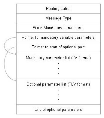
Some of important parameters are Called Party Address (GT,SSN,PC), (SCCP) Protocol Class etc.
TCAP:
Transaction Capabilities Application Part (TCAP) [Under SS7]
As we have seen in earlier articles, there is a need for switches to interact with each other for purposes other than call circuit setup. We need a layer on top of originating point-to-destination point connectivity provided by SCCP, that would help SSP/SCPs to do transactions with each other. We have already seen a pizza example wherein, SSP need to do a transaction "database query" with SCP. Another example would be callback feature.
A call B, but B is busy. Now A can request "callback on B". Once B goes on-hook, somehow this is to be informed back to A. If A and B are on one switch/SSP, it is an easy task. But if A and B are on different SSPs, somehow A's SSP need to inform to B's SSP about "A's request for callback".
TCAP itself will not implement these features, but will provide a (supporting) framework on which applications can be developed to provide these features. One popular user of TCAP is MAP (Mobile Application Part) used thoroughly in GSM networks for MSC/HLR/VLR interactions (e.g. signaling required to find the terminating mobile during call termination, location update related signaling etc.)
TCAP use connection-less services of SCCP. Note that the way TCAP has been specified in Q.771, instead of SCCP, other implementation of OSI network layer (providing required services) can be used.
TCAP has two sub-layers - transaction sublayer and component sublayer on top of it. This is evident in TCAP message structure as below. It uses ASN.1 format - it has "Tag", "Length", and "Value". "Tag" identifies the type of "Value". Length of "Value" is variable and so mentioned in "Length" field.
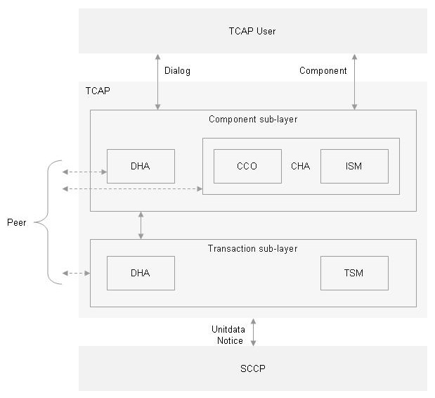
DHA - Dialogue Handling
CCO - Component Coordinator
CHA - Component Handling
ISM - Invocation State Machine
TCO - Transaction Coordinator
TSM - Transaction State Machine
CCO - Component Coordinator
CHA - Component Handling
ISM - Invocation State Machine
TCO - Transaction Coordinator
TSM - Transaction State Machine
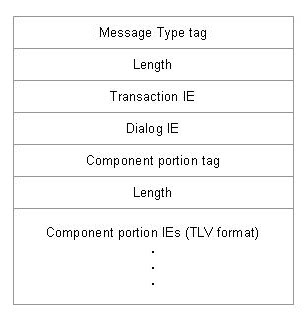
TCAP message is partitioned in three portions, Transaction, Component, and Dialog.
Transaction portion takes care of identifying transaction, Component contain the actual application data, whereas optional Dialog is used to know the version of transaction and encryption information between two nodes.
Transaction portion:
Transaction portion helps in identifying the transactions (and which would probably map to TCAP user who is involved in the transaction). Transaction Identifier is an important parameter here. There will be two transaction IDs here: originating and destination, assigned by respective nodes.
Transaction portion contain a message type which tells about the type of transaction message being sent. Possible values are:
UNIDIRECTIONAL: Message is being sent in one direction only and does not require response (return) message
BEGIN: This is used to initiate a transaction, but destination point may end the transaction.
END: This ends the transaction. It is normally final reply to BEGIN.
CONTINUE: When the transaction need to be continued, CONTINUE is used. Destination point, after receiving BEGIN, would send back this portion to let Originating point know that the transaction can be continued.
ABORT: This to terminate transaction due to abnormal situation. P-abort signifies that the transaction is aborted by protocol errors (like invalid values/tags etc.). U-abort is due to abort by TCAP user.
Component portion
With Transaction portion, TCAP provide a framework for multiple transactions. With component portion, TCAP provide flexibility of having multiple operations under one transaction. Component portion contain information related to component, relation of a component with earlier components, and the actual operation information.
Types of a component are; INVOKE (last/not last), RETURN RESULT (last/not last), RETURN ERROR, and REJECT.
INVOKE component, as the name suggests, invokes an operation. Last/Not last signifies if there are any further components.
RETURN result is used to return the results of an Invoke.
REJECT is protocol error, TCAP not able to process it possibly. Examples may be length not correct, invalid values etc.
RETURN ERROR is an operational error like unavailable resource, unauthorised request etc.
Note that Return result may itself contain an error happened at TCAP user level.
Correlation ID is used to correlate the component to earlier received components.
In addition, component portion contain operation codes and the parameters related to operation. Operation codes and parameters are implementation specific, but may still be standardised (like MAP/GSM)
Dialog portion
Dialog portion is an optional component. This contain an additional information like protocol version, encryption (security context), application that is to be addressed (application context) etc. Dialog could be structured dialog or unstructured one. Unstructured dialog is basically a one time transmission with no expectation for response from received. In structured dialog, dialog portion would contain DIALOG BEGIN (X.227-AARQ), DIALOG CONFIRM (X.227-AARE), or DIALOG ABORT (X.227-ABRT).
A popular user of Dialog portion is MAP/GSM. In MAP, application context name is used; it will have information about MAP module and version. Using this, appropriate software module can be chosen to process the transaction.
Example of TCAP portions
Let us say, entity A would like to begin transaction with entity B - TCAP message may contain BEGIN transaction portion, (optional) DIALOG BEGIN/AARQ dialog component, and INVOKE component.
B may reply back with CONTINUE, AARE, and RETURN !
Primitives
Dialog handling primitives are:
TC-NOTICE (Ind/Req)
TC-UNI (Ind/Req)
TC-BEGIN (Ind/Req)
TC-CONTINUE (Ind/Req)
TC-END (Ind/Req)
TC-U-ABORT (Ind/Req)
TC-P-ABORT (Ind)
TC-UNI (Ind/Req)
TC-BEGIN (Ind/Req)
TC-CONTINUE (Ind/Req)
TC-END (Ind/Req)
TC-U-ABORT (Ind/Req)
TC-P-ABORT (Ind)
Component handling primitives are:
TC-INVOKE (Ind/Req)
TC-RESULT-L (Ind/Req)
TC-RESULT-NL (Ind/Req)
TC-U-ERROR (Ind/Req)
TC-L-CANCEL (Ind)
TC-U-CANCEL (Ind)
TC-R-REJECT (Ind)
TC-L-REJECT (Ind)
TC-U-REJECT (Ind/Req)
TC-RESULT-L (Ind/Req)
TC-RESULT-NL (Ind/Req)
TC-U-ERROR (Ind/Req)
TC-L-CANCEL (Ind)
TC-U-CANCEL (Ind)
TC-R-REJECT (Ind)
TC-L-REJECT (Ind)
TC-U-REJECT (Ind/Req)
ISUP:
ISDN User Part
ISDN stand for Integrated Services Digital Network. Basic idea of ISDN was to provide digital link directly to subscriber and provide both voice and data over same (circuit switched) link. Link itself will have multiple channels which can be dynamically allocated depending on data rate. ISDN also separated signaling from transmission, D channels carrying signaling and B channel carrying data. B channels will typically be multiples of 64 kpbs. D channel would be 16 kbps (Basic Rate Interface/BRI) or 64 kbps (Primary Rate Interface/PRI) or multiples of it.
Though powerful, ISDN lacked the standardisation on network side. Without end-to-end ISDN connectivity, complete potential of ISDN was not realised until SS7. With SS7, ISDN was able to provide end-to-end (digital) connectivity. ISDN was accommodated in SS7 as ISDN User Part.
ISUP provide signaling required for voice/data connections between SSPs. (D channel) Signaling goes over (STP) signaling network whereas SSPs are connected via transmission network (B channels).
Let us see how ISUP setup the call.

A calls B. A and B are located on different exchange. The call is required to go through OE (originating exchange), TE (transit exchange) and DE (destination exchange). Exchanges are nothing but SSPs.

1) OE translates the digits (dialed by A) and finds out that the call need to routed to TE. To do it, it sends (ISUP) Initial Address Message (IAM) - containing called number, calling number, type of call etc. information - to TE. OE also activates backward direction transmission link to A.
2) TE again translates on called number received in IAM and finds out that the call need to be routed to DE. Note that the network operator need to make sure that the appropriate "translation tables" are present in exchanges. To do it, it sends out another IAM - most of the information transparently taken from IAM received from OE - to DE. At the same time, TE may reserve or connect a transmission link between OE and TE in backward or both directions. In practice, a backward direction link is connected.
3) DE finds out - from IAM received from TE - that called number is within its area. As B is not busy, it sends Address Complete Message (ACM) back to TE and reserve or connect the transmission link between DE and TE in backward or both directions (in practice backward direction link). After receiving ACM, TE also sends ACM back to OE. ACM can actually be considered as "called party B ringing". At this point DE may also provide a "ringing tone" over transmission link (if connected). B also sends out ringing to B.
4) Once B answers, DE sends out Answer Message (ANM) to TE and simultaneously completes the transmission path on both directions if not done already. TE also sends out ANM to OE and completes the transmission path. OE too completes transmission link to A. Now A and B are in conversation.
Release (REL) message is used during call teardown (reason would be called party busy, called party did not answer, or normal call release etc.). Reply to REL message Release Complete (RLC).
ISUP provide two types of services: Basic and Supplementary. Basic service is nothing but Call setup and Tear down procedures. Supplementary services deals messages related to call path already established e.g. Call waiting, Call forward (during call) etc. Supplementary services are not defined separately but parameters within certain messages helps in implementing them e.g. "service activation" parameter in "Facility" message.
In addition, ISUP is flexible to provide end-to-end signaling. Let us say a network operator comes with a beautiful feature which require originating and destination exchanges to exchange certain operator specific (proprietary) information. This could be done in number of ways e.g. with "Pass Along Message" or "User-to-user information" parameter in IAM and other messages. Note that the information travel same path as the IAM message path.
Alternative for end-to-end signaling is to use SCCP to transfer the information directly to destination exchange through STP network ! In practice though ISUP method is preferred.
ISUP use MTP services for its message transfer; ISUP message is filled into SIF of MTP message. ISUP message consist of Circuit Identification Code (CIC) followed by Message type and related parameters. Parameters are coded as "Mandatory fixed parameters" followed by "Mandatory variable parameters" and then "Optional parameters" at the end (similar to SCCP message format with addition of CIC before Message type).
Circuit Identification Code (CIC) indicate the circuit that is being setup or released. It is 2 octet long and is to be agreed among telephone companies.
This complete the brief on ISUP.
Telephone User Part (TUP)
TUP is used for circuit connection setup and tear down. Initially SS7 used TUP instead of ISUP, later however TUP was found to be limited in comparison to ISDN in terms of capabilities (flexibilities). And so ISUP was added to SS7 an alternative to TUP. TUP has been defined in Q.721 thru Q.725. It was mainly used in European countries. It is also being used in China. TUP has been replaced by ISUP in most of the world. TUP is not dealt here.
SS7 points and their protocol layers [Under SS7]
Below diagram shows SS7 points with their protocol layers.
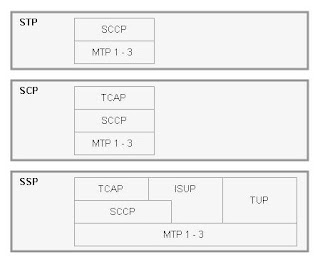
This complete the brief on SS7.